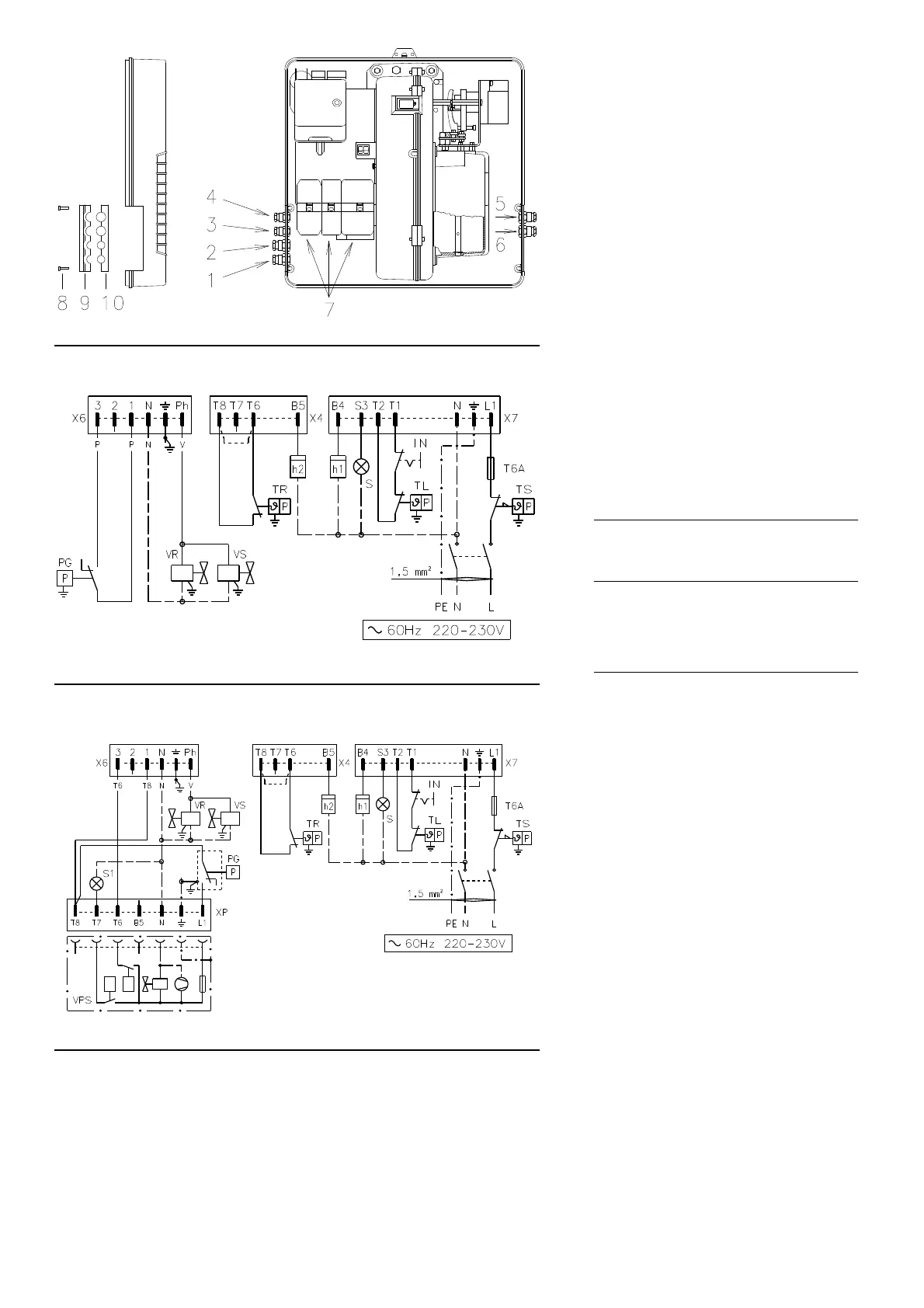
10
ELECTRICAL CONNECTIONS
Use flexible cables according to EN 60 335-1
Regulations:
• if in PVC sheath, use at least H05 VV-F
• if in rubber sheath, use at least H05 RR-F.
All the wires to connect to the burner plugs 7)(A)
must enter through the supplied fairleads, which
must be fitted into the relevant holes in the left
hand or right hand plate. To do this, first
unscrew screws 8), then split the plate into its
parts 9) and 10) and remove the menbrane
press-outs from the holes.
The fairleads and hole press-outs can be in var-
ious ways; the following lists show one possible
solution:
RS 28 und RS 38 single-phase
1 -Pg 11 Single-phase power supply
2 -Pg 11 Gas valves
3 -Pg 9 Remote control device TL
4 -Pg 9 Remote control device TR
5 -Pg 11 Gas pressure switch or gas valve
leak detection control device
RS 38 three-phase and RS 50
1 -Pg 11 Three-phase power supply
2 -Pg 11 Single-phase power supply
3 -Pg 9 Remote control device TL
4 -Pg 9 Remote control device TR
5 -Pg 11 Gas valves
6 -Pg 11 Gas pressure switch or gas valve
leak detection control device
LAYOUT (B) - The RS 28 - 38 Models electrical
connection single-phase power supply
without leak detection control device.
LAYOUT (C) The RS 28 - 38 Models electrical
connection single-phase power supply
with VPS leak detection control device.
Gas valve leak detection control takes place
immediately before every burner start-up.
Key to layouts (B) - (C)
h1 - 1st stage hourcounter
h2 - 2nd stage hourcounter
IN - Burner manual stop switch
XP- Plug for leak detection control device
X4 - 4 pole plug
X6 - 6 pole plug
X7 - 7 pole plug
PC- Gas pressure switch for leak detection con-
trol device
PG- Min. gas pressure switch
S - Remote lock-out signal
S1 - Remote lock-out signal of leak detection
control device
TR- High-low mode load remote control system:
controls operating stages 1 and 2.
If the burner is to be set up for single stage
operation, replace of remote control device
TR with a jumper.
TL - Load limit remote control system:
shuts down the burner when the boiler tem-
perature or pressure reaches the preset
value.
TS- Safety load control system:
operates when TL is faulty
VR- Adjustment valve
VS- Safety valve
(A)
(B)
RS 28 - RS 38 single-phase without leak detection control device
RS 28 - RS 38 single-phase with leak detection control device VPS
(C)
D3027
D3161
D3162