3
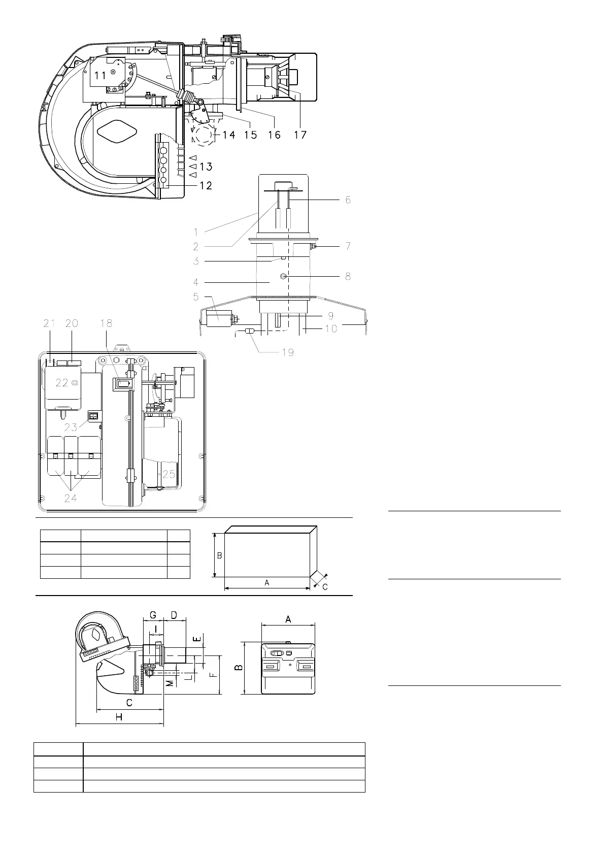
BURNER DESCRIPTION (A)
1 Combustion head
2 Ignition electrode
3 Screw for combustion head adjustment
4 Sleeve
5 Minimum air pressure switch
(differential operating type)
6 Flame sensor probe
7 Air pressure test point
8 Gas pressure test point and head fixing screw
9 Screws securing fan to sleeve
10 Slide bars for opening the burner and
inspecting the combustion head
11 Servomotor controlling the gas butterfly
valve and of air gate valve (by means of a
variable profile cam mechanism).
When the burner is not operating the air gate
valve is fully closed in order to reduce heat
dispersion from the boiler due to the flue
draught which draws air from the fan suction
inlet.
12 Plate with four hole knock-outs for electrical
cable routing
13 Air inlet to fan
14 Gas input pipework
15 Gas butterfly valve
16 Boiler mounting flange
17 Flame stability disk
18 Flame inspection window
19 Plug-socket on ionisation probe cable
20 Motor contactor and thermal cut-out reset
button (RS 38 - 50 three-phase)
21 Motor capacitor (RS 28 - 38 single-phase)
22 Control box with lock-out pilot light and lock-
out reset button
23 Two switches:
- one “burner off - on”
- one for “1st - 2nd stage operation”
24 Plugs for electrical connections
25 Air gate valve
Two types of burner failure may occur:
• Control box lock-out: if the control box
22)(A) pushbutton (red led) lights up, it indi-
cates that the burner is in lock-out.
To reset, hold the pushbutton down for
between 1 and 3 seconds.
• Motor trip (RS 38 three-phase - RS 50):
release by pressing the pushbutton on ther-
mal cutout 20)(A).
PACKAGING - WEIGHT (B) - Approximate
measurements
• The burner are shipped in cardboard boxes with
the maximum dimensions shown in Table (B).
• The weight of the burner complete with pack-
aging is indicated in table (B).
MAX. DIMENSIONS (C)
Approximate measurements
The maximum dimensions of the burner are
given in (C).
Note that if you need to examine the combustion
head, the burner must be pulled backward on
the slide bars and turned upward.
The maximum dimension of the burner, without
the cover, when open is give by measurement
H.
STANDARD EQUIPMENT
1 - Gas train flange
1 - Flange gasket
4 - Flange fixing screws M 8 x 25
1 - Thermal insulation screen
4 - Screws to secure the burner flange to the
boiler: M 8 x 25
5 - Fairleads for electrical connections
(RS 28 - 38 single-phase)
6 - Fairleads for electrical connections
(RS 38 - 50 three-phase)
1 - Instruction booklet
1 - Spare parts list
(A)
mm A B C kg
RS 28 1010 625 495 38
RS 38 1010 625 495 40
RS 50 1010 625 495 41
(B)
(1) Blast tube: short-long
mm A B C D
(1)
E F G H I L M
RS 28 476 474 580 216 - 351 140 352 164 810 108 168 1”1/2
RS 38 476 474 580 216 - 351 140 352 164 810 108 168 1”1/2
RS 50 476 474 580 216 - 351 152 352 164 810 108 168 1”1/2
(C)
D492
D88
D3045
D3026
D495