6
INSTALLATION
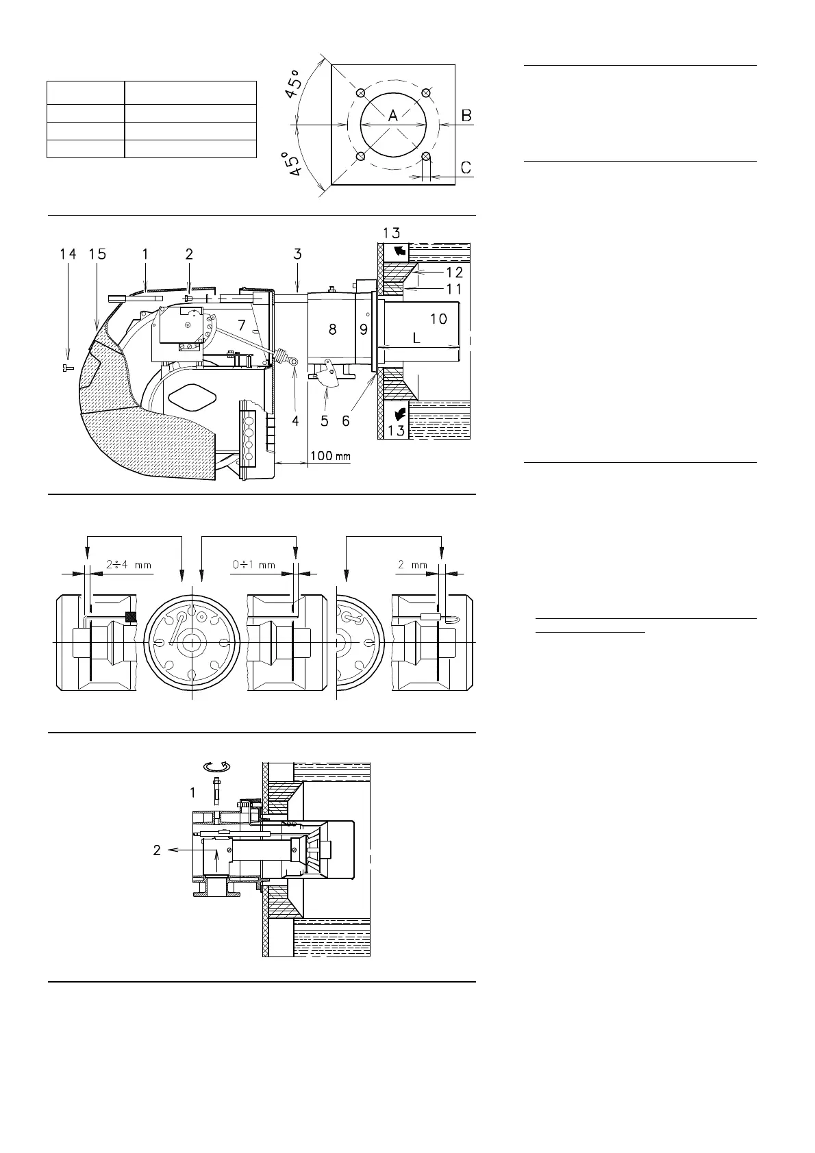
BOILER PLATE (A)
Drill the combustion chamber locking plate as
shown in (A).
The position of the threaded holes can be
marked using the thermal screen supplied with
the burner.
BLAST TUBE LENGTH (B)
The length of the blast tube must be selected
according to the indications provided by the
manufacturer of the boiler, and in any case it
must be greater than the thickness of the boiler
door complete with its fettling. The range of
lengths available, L (mm), is as follows:
Blast tube 10): RS 28 RS 38 RS 50
• short 216 216 216
• long 351 351 351
For boilers with front flue passes 13) or flame
inversion chambers, protective fettling in refrac-
tory material 11) must be inserted between the
boiler fettling 12) and the blast tube 10).
This protective fettling must not compromise the
extraction of the blast tube.
For boilers having a water-cooled front the
refractory fettling 11)-12)(B) is not required
unless it is expressly requested by the boiler
manufacturer.
SECURING THE BURNER TO THE BOILER (B)
Before securing the burner to the boiler, check
through the blast tube opening to make sure
that the flame sensor probe and the ignition
electrode are correctly set in position, as shown
in (C).
Now detach the combustion head from the
burner, fig.(B):
- remove screw 14) and withdraw the cover
15).
- Disengage the articulated coupling 4) from
the graduated sector 5).
- Remove the screws 2) from the slide bars 3)
- Remove screw 1) and pull the burner back on
slide bars 3) by about 100 mm.
Disconnect the wires from the probe and the
electrode and then pull the burner completely
off the slide bars, after removing the split pin
from the slide bar 3).
Secure the flange 9)(B) to the boiler plate, inter-
posing the thermal insulating screen 6)(B) sup-
plied with the burner. Use the 4 screws, also
supplied with the unit, after first protecting the
thread with an anti-locking product.
The seal between burner and boiler must be air-
tight.
If you noticed any irregularities in positions of
the probe or ignition electrode during the check
mentioned above, remove screw 1)(D), extract
the internal part 2)(D) of the head and proceed
to set up the two components correctly.
Do not attempt to turn the probe. Leave it in the
position shown in (C) since if it is located too
close to the ignition electrode the control box
amplifier may be damaged.
(A)
(B)
mm A B C
RS 28 160 224 M 8
RS 38 160 224 M 8
RS 50 160 224 M 8
(C)
(D)
PROBE ELECTRODE RS 28-38 ELECTRODE RS 50
D455
D499
D880
D501