5
GAS PRESSURE
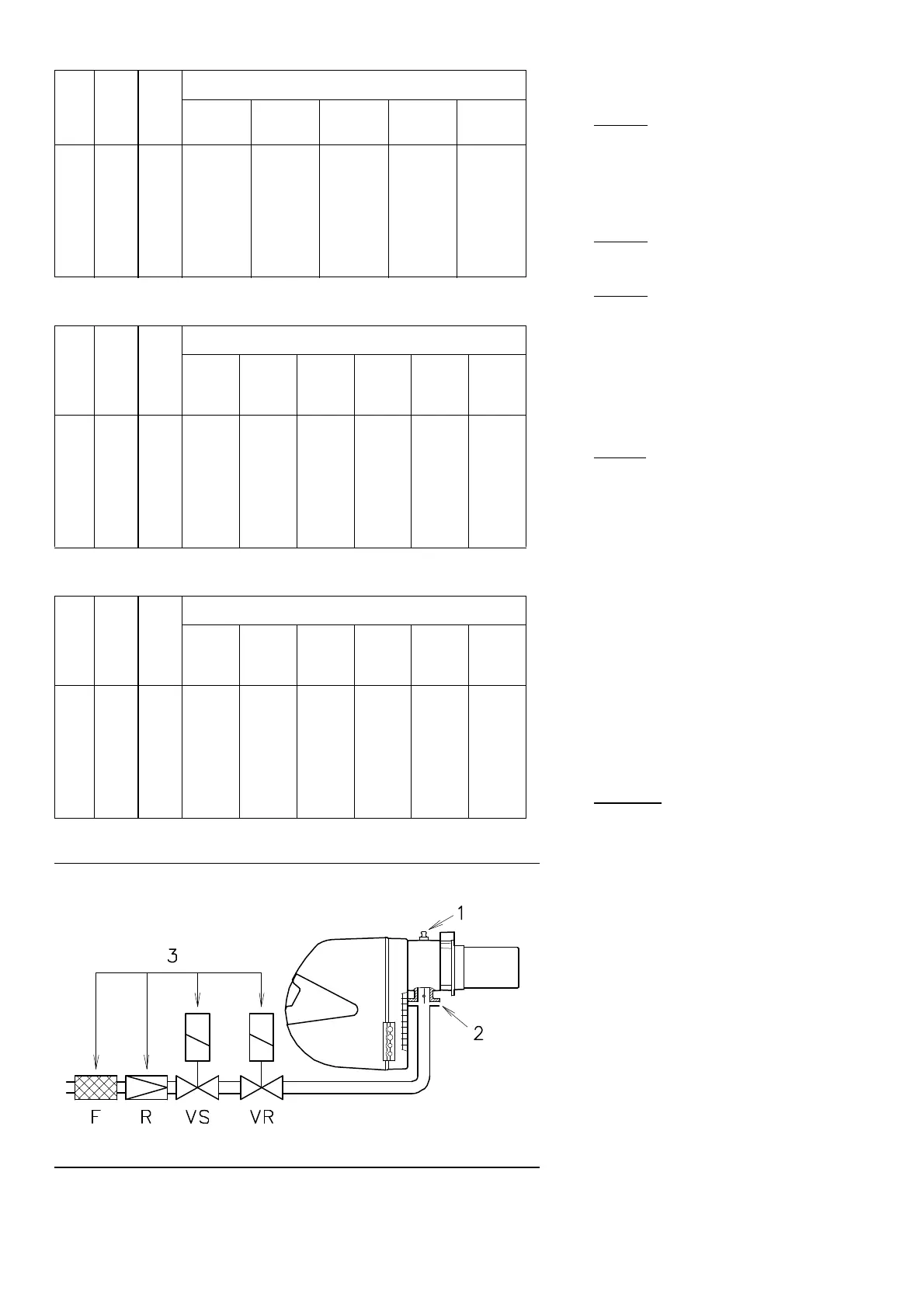
The adjacent tables show minimum pressure
losses along the gas supply line depending on
the burner output in 2nd stage operation.
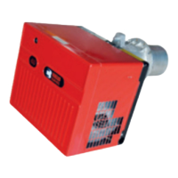
Column 1
Pressure loss at combustion head.
Gas pressure measured at test point 1)(B), with:
• Combustion chamber at 0 mbar
• Burner operating in 2nd stage
• Gas ring 2)(B)p.7 adjusted as indicated in dia-
gram (C)p. 7.
Column 2
Pressure loss at gas butterfly valve 2)(B) with
maximum opening: 90°.
Column 3
Pressure loss of gas train 3)(B) includes: adjust-
ment valve VR, safety valve VS (both fully
open), pressure governor R, filter F.
The values shown in the various tables refer to:
natural gas G20 PCI 10 kWh/Nm
3
(8.6 Mcal/Nm
3
).
With:
natural gas G25 PCI 8.6 kWh/Nm
3
(7.4 Mcal/Nm
3
)
multiply tabulated values by 1.3.
Calculate the approximate 2nd stage output of
the burner thus:
- subtract the combustion chamber pressure
from the gas pressure measured at test point
1)(B).
- Find the nearest pressure value to your result
in column 1 of the table for the burner in ques-
tion.
- Read off the corresponding output on the left.
Example - RS 28:
• 2nd stage operation
• Natural gas G20 PCI 10 kWh/Nm
3
• Gas ring 2)(B)p.7 adjusted as indicated in dia-
gram (C)p.7.
• Gas pressure at test point 1)(B) = 6 mbar
• Pressure in combustion chamber = 2 mbar
6 - 2 = 4 mbar
A 2nd stage output of 210 kW shown in Table RS
28 corresponds to 4 mbar pressure, column 1.
This value serves as a rough guide, the effective
delivery must be measured at the gas meter.
To calculate the required gas pressure at test
point 1)(B), set the output required from the
burner in 2nd stage operation:
- find the nearest output value in the table for
the burner in question.
- Read off the pressure at test point 1)(B) on
the right in column 1.
- Add this value to the estimated pressure in
the combustion chamber.
Example - RS 28:
• Required burner output in 2nd stage opera-
tion: 210 kW
• Natural gas G20 PCI 10 kWh/Nm
3
• Gas ring 2)(B)p.7 adjusted as diagram (C)p.7.
• Gas pressure at burner output of 210 kW,
taken from table RS 28, column 1 = 4 mbar
• Pressure in combustion chamber = 2 mbar
4 + 2 = 6 mbar
pressure required at test point 1)(B).
(A)
(B)
RS 28 ∆p (mbar)
RS 38 ∆p (mbar)
RS 50 ∆p (mbar)
kW 1 2
3
Ø
3/4
3970076
Ø 1”
3970077
Ø 1”
1/4
3970144
Ø 1”
1/2
3970145
Ø 1”
1/2
3970180
165
185
210
235
260
285
310
325
2,5
3,1
4,0
4,7
5,5
6,3
7,0
7,5
0,1
0,1
0,1
0,2
0,2
0,3
0,3
0,3
11,1
13,4
16,5
19,9
23,6
27,5
31,6
34,2
5,3
6,4
7,9
9,5
11,2
13,1
15,0
16,2
3,2
3,8
4,7
5,6
6,6
7,6
8,7
9,4
2,1
2,5
3,1
3,8
4,5
5,3
6,2
6,7
1,8
2,0
2,5
3,2
3,7
4,4
4,7
4,9
kW 1 2
3
Ø 1”
3970077
Ø 1”
1/4
3970144
Ø 1”
1/2
3970145
Ø 1”
1/2
3970180
Ø 2”
3970146
3970160
Ø 2”
3970181
3970182
230
260
290
320
350
380
410
440
2,6
3,1
3,7
4,3
4,8
5,4
6,0
6,6
0,2
0,2
0,3
0,3
0,4
0,4
0,5
0,6
9,2
11,2
13,4
15,8
18,3
20,9
23,7
26,6
5,4
6,6
7,9
9,2
10,6
12,1
13,7
15,3
3,6
4,5
5,5
6,5
7,6
8,8
10,1
11,4
3,0
3,7
4,4
4,8
5,9
6,6
7,0
8,1
1,4
1,7
2,1
2,5
3,0
3,5
4,0
4,5
1,8
2,2
2,7
3,3
3,5
4,0
4,4
5,0
kW 1 2
3
Ø 1”
3970077
Ø 1”
1/4
3970144
Ø 1”
1/2
3970145
Ø 1”
1/2
3970180
Ø 2”
3970146
3970160
Ø 2”
3970181
3970182
290
330
370
410
450
490
530
580
2,2
2,9
3,6
4,3
5,0
5,6
6,3
7,2
0,3
0,4
0,5
0,6
0,7
0,9
1,0
1,2
13,4
16,6
20,0
23,7
27,6
31,7
36,1
41,8
7,9
9,7
11,6
13,7
15,9
18,2
20,6
23,9
5,5
6,9
8,4
10,1
11,9
13,7
15,7
18,5
4,4
5,0
6,1
7,0
8,3
9,7
10,5
12,0
2,1
2,7
3,3
4,0
4,7
5,5
6,3
7,4
2,7
3,4
3,9
4,4
5,1
5,9
6,6
7,8
D934