11
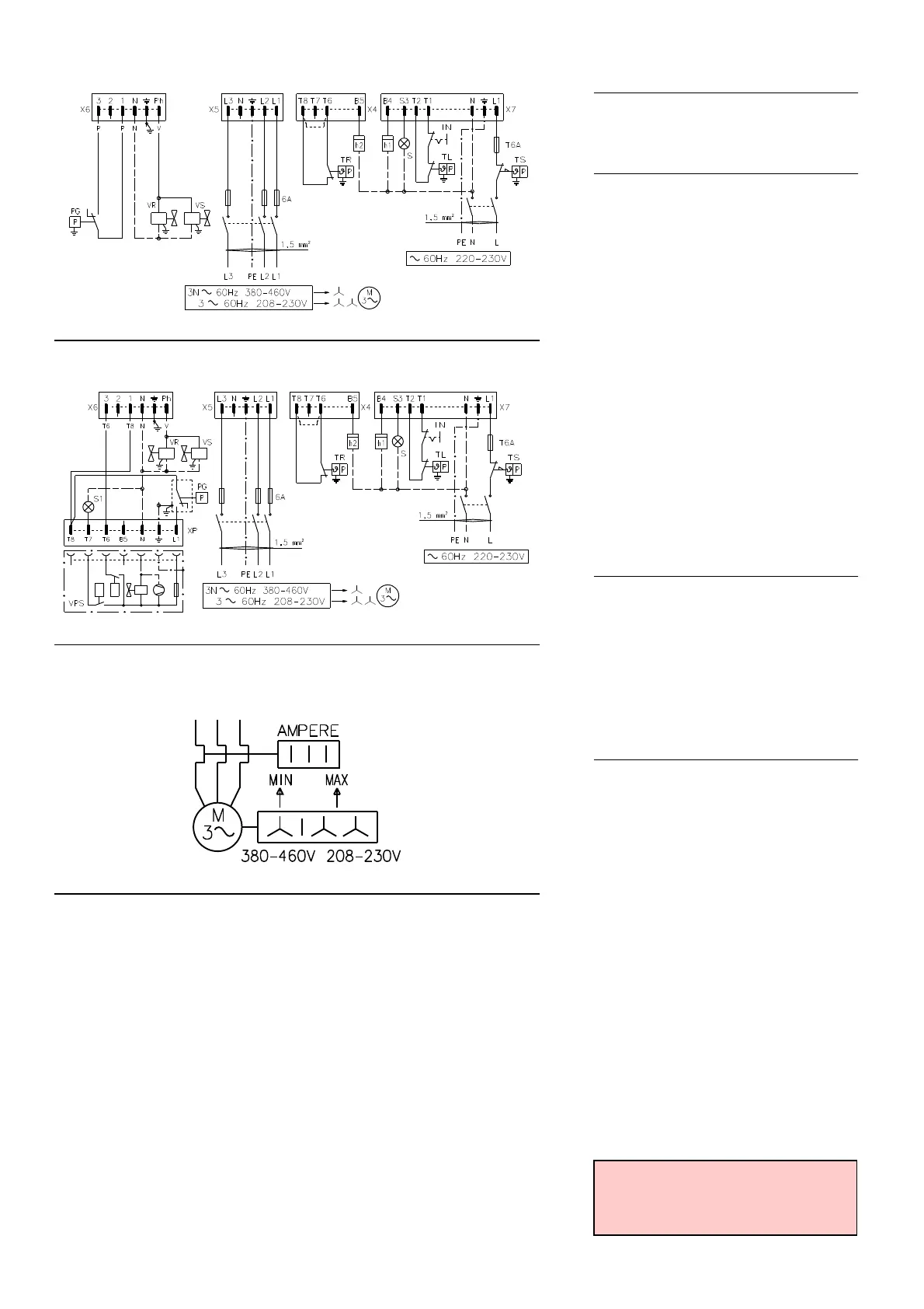
LAYOUT (A) - The RS 38 - 50 Models electri-
cal connection three-phase power supply
without leak detection control device
LAYOUT (B) - The RS 38 - 50 Models electri-
cal connection three-phase power supply
with VPS leak detection control device.
Gas valve leak detection control takes place
immediately before every burner starting.
Key to layouts (A) - (B)
h1 - 1st stage hourcounter
h2 - 2nd stage hourcounter
IN - Burner manual stop switch
XP- Plug for leak detection control device
X4 - 4 pole plug
X5 - 5 pole plug
X6 - 6 pole plug
X7 - 7 pole plug
PC- Gas pressure switch for leak detection con-
trol device
PG- Min. gas pressure switch
S - Remote lock-out signal
S1 - Remote lock-out signal of leak detection
control device
TR- High-low mode load remote control system:
controls operating stages 1 and 2.
If the burner is to be set up for single stage
operation, replace of remote control device
TR with a jumper.
TL - Load limit remote control system:
shuts down the burner when the boiler tem-
perature or pressure reaches the preset
value.
TS- Safety load control system:
operates when TL is faulty
VR- Adjustment valve
VS- Safety valve
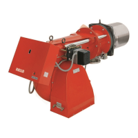
LAYOUT (C)
Calibration of thermal cut-out 20)(A)p.3
This is required to avoid motor burn-out in the
event of a significant increase in power absorp-
tion caused by a missing phase.
• If the motor is double star-powered, 380-460
V, the cursor should be positioned to "MIN".
• If the motor is star-powered, 208-230 V, the
cursor should be positioned to "MAX".
Even if the scale of the thermal cut-out does not
include rated motor absorption at 380-460 V,
protection is still ensured in any case.
N.B.
• The RS 38 and RS 50 three-phase leave the
factory preset for 380-460 V power supply. If
208-230 V power supply is used, change the
motor connection from star to double star
and change the setting of the thermal
cut-out as well.
• The supply to the auxiliary circuits must be
220-230 V.
• The RS 28-38-50 burners have been type-
approved for intermittent operation. This
means they should compulsorily be stopped
at least once every 24 hours to enable the
control box to check its own efficiency at start-
up. Burner halts are normally provided for
automatically by the boiler load control sys-
tem. If this is not the case, a time switch
should be fitted in series to IN to provide for
burner shut-down at least once every 24
hours.
• The RS 28-38-50 burners are factory set for
two-stage operation and must therefore be
connected to control device TR. Alternatively,
if single stage operation is required, instead of
control device TR install a jumper lead
between terminals T6 and T8 of connector X4.
WARNING: Do not invert the neutral with
the phase wire in the electricity supply
line. Inverting the wires will make the
burner go into lock-out because of firing
failure.
(A)
(B)
RS 38 - RS 50 three-phase without leak detection control device
RS 38 - RS 50 three-phase without leak detection control device VPS
(C)
CALIBRATION OF THERMAL RELAY
RS 38 three-phase - RS 50
D3163
D3164
D3165