9
20135920
Technical description of the burner
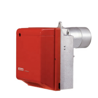
5.3 Maximum dimensions
The maximum dimensions of the flange and burner are given in Fig. 1.
Tab. D
5.4 Burner equipment
Flange with insulating gasket .............................................No. 1
Screw and nuts for flange ...................................................No. 1
Remote reset connection ...................................................No. 1
Screws and nuts for fixing the flange to the boiler............... No. 4
Flexible hoses with nipples ................................................. No. 2
4 pin plug ............................................................................No. 1
Installer booklet ...................................................................No. 1
Spare Parts List...................................................................No. 1
Remote reset kit
The burner has a remote reset kit (RS) consisting of a con-
nection and a push-button operating at a distance of 20
metres max.
In order to install it, remove the safety lockout device installed
at the factory and insert the lockout supplied with the burner
(see electrical diagram).
D7146
D
E - E1 A
B
C
ØH
F
G
189
106
168
140
4
5
°
4
5
°
11
8383
213
160
190
1
1
99
99
127
4
5
°
4
5
°
394T1
397T1
398T1
380T1
E = Short head
E1 = Long head
Type A B C D E E1 F G
ØH
380T1 255 280 230 202 115 180 10 28 95
394T1 300 345 285 228 142 210 12 36 123
397T1 300 345 285 228 142 210 12 36 123
398T1 300 345 285 247 159 300 12.5 36 125