25
20135920
Start-up, calibration and operation of the burner
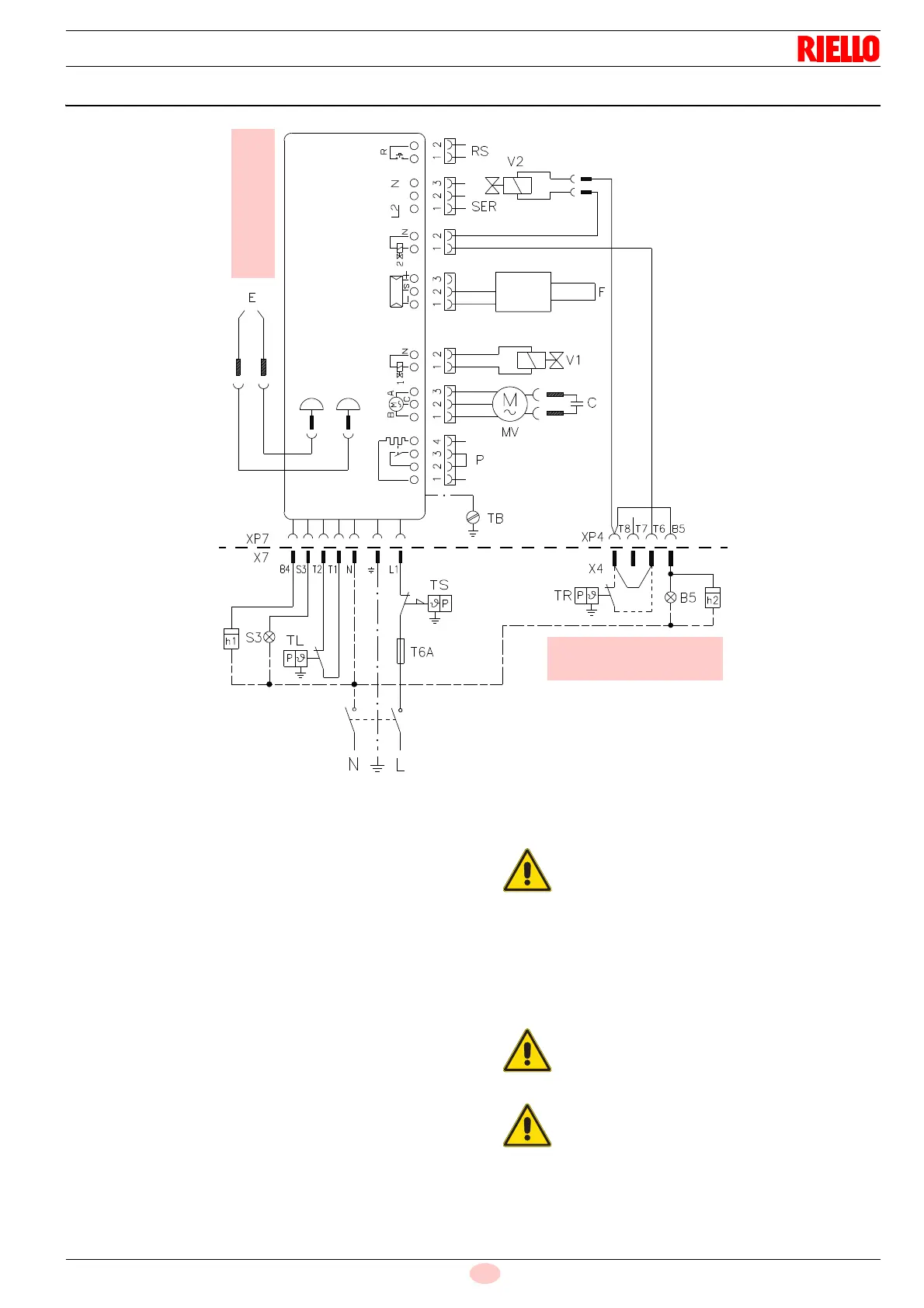
7.5 Electrical diagram
KEY TO LAY-OUT:
B5 – 2nd stage operation signal (230V
~- 0.1A max.)
C – Capacitor
E –Electrode
F – Flame sensor
h.. – Hour counter (230V ~ - 0.1A max.)
MV – Motor
P – Bridge socket
RS – Remote reset
S3 – Remote lockout signal (230V ~- 0.5A max.)
SER – Safety lockout device
T6A –Fuse
TB – Burner-earth
TL – Limit thermostat
TR – Adjustment thermostat
TS – Safety thermostat
V1 – Oil valve 1st stage
V2 – Oil valve 2nd stage
X.. –Plug
XP.. – Socket
230V ~ 50Hz
Fig. 23
CONTROL BOX
20148677
Master
switch
CARRIED OUT
IN THE FACTORY
TO BE DONE BY
BY THE INSTALLER
Do not invert the neutral with the phase in the
electrical supply line.
Check that the electrical supply of the burner
corresponds to that shown on the identifica-
tion label and in this manual.
The section of the conductors must be at
least 1mm
2
. (Unless requested otherwise by
local standards and legislation).
Connect the 2nd stage thermostat (TR) to the
terminals T6 - T8 removing the jumper.
Test the burner by checking the shut-down of the
burner by opening the thermostats and the lockout
by blocking out the flame sensor.
If the cover is still on, remove it and proceed with
the electric wiring following the wiring diagrams.
Use flexible cables in compliance with EN 60 335-
1 standards.