23
20135920
Start-up, calibration and operation of the burner
7.1 Notes on safety for the first start-up
7.2 Combustion adjustment
In conformity with EN 267, the installation of the burner on the
boiler, the adjustment and testing must be carried out in compli-
ance with the instruction manual of the boiler, including control of
the CO and CO
2
concentration in the flue gases, their tempera-
ture and the average temperature of the water in the boiler.
To suit the required boiler output, choose the proper nozzle and
adjust the pump pressure and the air damper opening in accord-
ance with the following data. The values in Tab. I are obtained on
the boiler (according to EN267).
They refer to 12.5 % CO
2
, at sea level and with an ambient and
light oil temperature of 20 °C.
Tab. I
7 Start-up, calibration and operation of the burner
The first start-up of the burner must be carried out
by qualified personnel, as indicated in this manual
and in compliance with the standards and regula-
tions of the laws in force.
Check the correct working of the adjustment, com-
mand and safety devices.
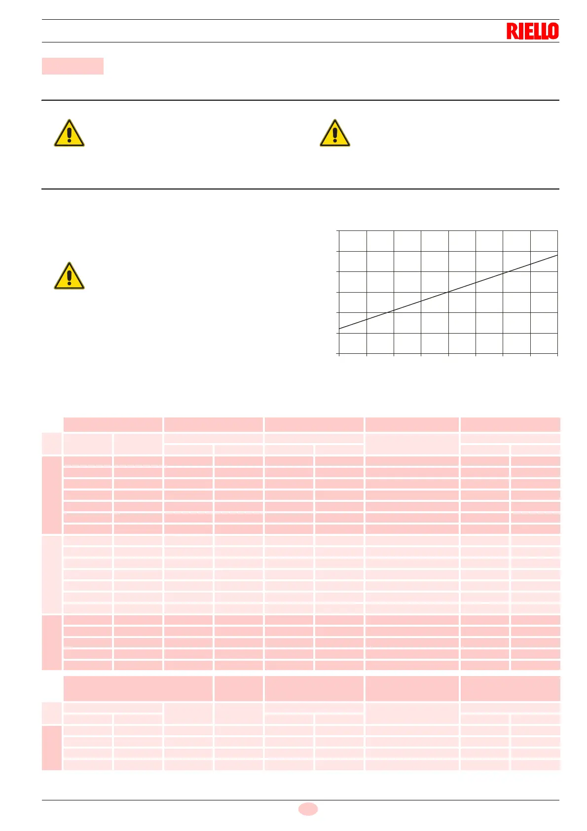
The temperature of the combustion air (relative to
the place where the burner is installed) may vary
during the season, it influences the CO
2
of the
burner. We recommend adjusting the CO
2
based
upon the temperature of the combustion air at the
time when the burner calibration is carried out in
accordance with what is shown in the following di-
agram.
Example Combustion air temperature =10°C ad-
just the CO
2
to 12.5%.
Fig. 22
Combustion air temperature
D4604
14.5
14.0
13.5
13.0
12.5
12.0
11.5
0 5 10 15 30
40
352520
% CO
2
Nozzle Pump pressure Burner output Adjust. comb. head Adjusting damper
GHP Angle
bar kg/h ± 4%
Set-point
Set-point
1st stage 2nd stage 1st stage 2nd stage 1st stage 2nd stage
380T1
1.00 60° 9 14 3.5 4.3 0 0.2 1.5
1.10 60° 9 14 3.8 4.8 1 0.4 2.1
1.25 60° 9 14 4.3 5.4 2 0.6 2.6
1.50 60° 9 14 5.2 6.5 3 0.8 3.4
1.75 60° 9 14 6.1 7.6 4 1.2 4.8
2.00 60° 9 14 7.0 8.7 5 1.4 5.4
2.25 60° 9 14 7.8 9.8 6 1.6 6.0
394T1
1.50 60° 9 15 5.3 6.8 0 0.2 0.5
1.75 60° 9 15 6.4 8.2 0.5 0.25 1.0
2.00 60° 9 15 7.2 9.3 1.5 0.4 1.1
2.25 60° 9 15 8.2 10.5 2.5 0.5 1.5
2.50 60° 9 15 8.7 11.2 3.5 0.6 2.0
3.00 60° 9 15 10.5 13.5 5.0 0.8 3.0
3.50 60° 9 14 12.5 15.2 6.0 1.0 3.9
397T1
2.50 60° 9 14 8.7 10.8 0 0.2 1.8
3.00 60° 9 14 10.4 13.0 1 0.5 2.7
3.50 60° 9 14 12.2 15.2 2.5 0.8 3.7
4.00 60° 9 14 13.9 17.3 4 1.0 4.5
4.50 60° 9 14 15.6 19.5 6 1.3 6.0
Nozzle
Pump
pressure
Burner output Adjust. comb. head Adjusting damper
GHP
Angle bar
kg/h ± 4%
Set-point
Set-point
1st stage 2nd stage 1st stage 2nd stage 1st stage 2nd stage
398T1
2.00 1.00 60° 12 8.0 12.4 0 0.25 2.1
2.00 2.00 60° 12 8.0 16.4 3 0.15 3.0
2.50 2.50 60° 12 10.3 20.5 6 0.3 4.4
3.00 3.00 60° 12.5 12.6 25.0 8 0.6 6.0