30
5.1.2. Adjusting the antenna
When the measurement diagnoses that the antenna is off the desired frequency, the
analyzer can help in adjusting it.
Physical dimensions of a simple antenna (such as a dipole) can be adjusted knowing
the actual resonant frequency and the desired one.
Other types of antennas may contain more than one element to adjust (including coils,
filters, etc.), so this method will not work. Instead, you may use the SWR mode, the
Show all mode or the Smith/polar chart mode to continuously see the results while
adjusting various parameters of the antenna.
For multi-band antennas, use the Multi SWR mode. You can easily see how changing
one of the adjustment elements (trimming capacitor, coil, or physical length of an
aerial) affects SWR at up to five different frequencies.
5.2. Coaxial lines
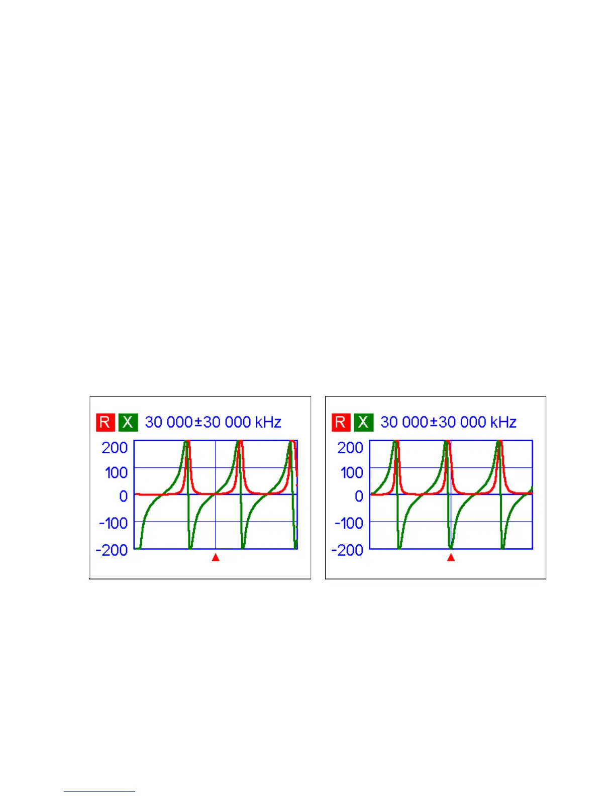
5.2.1. Open- and short-circuited cables
Open-circuited cable Short-circuited cable
The above pictures show R and X graphs for a piece of cable with open- and short-
circuited far end. A resonant frequency is a point at which X (reactance) equals to zero:
• In the open-circuited case, resonant frequencies correspond to (left to right) 1/4,
3/4, 5/4, etc. of the wavelength in this cable;
• For the short-circuited cable, these points are located at 1/2, 1, 3/2, etc. of the
wavelength.