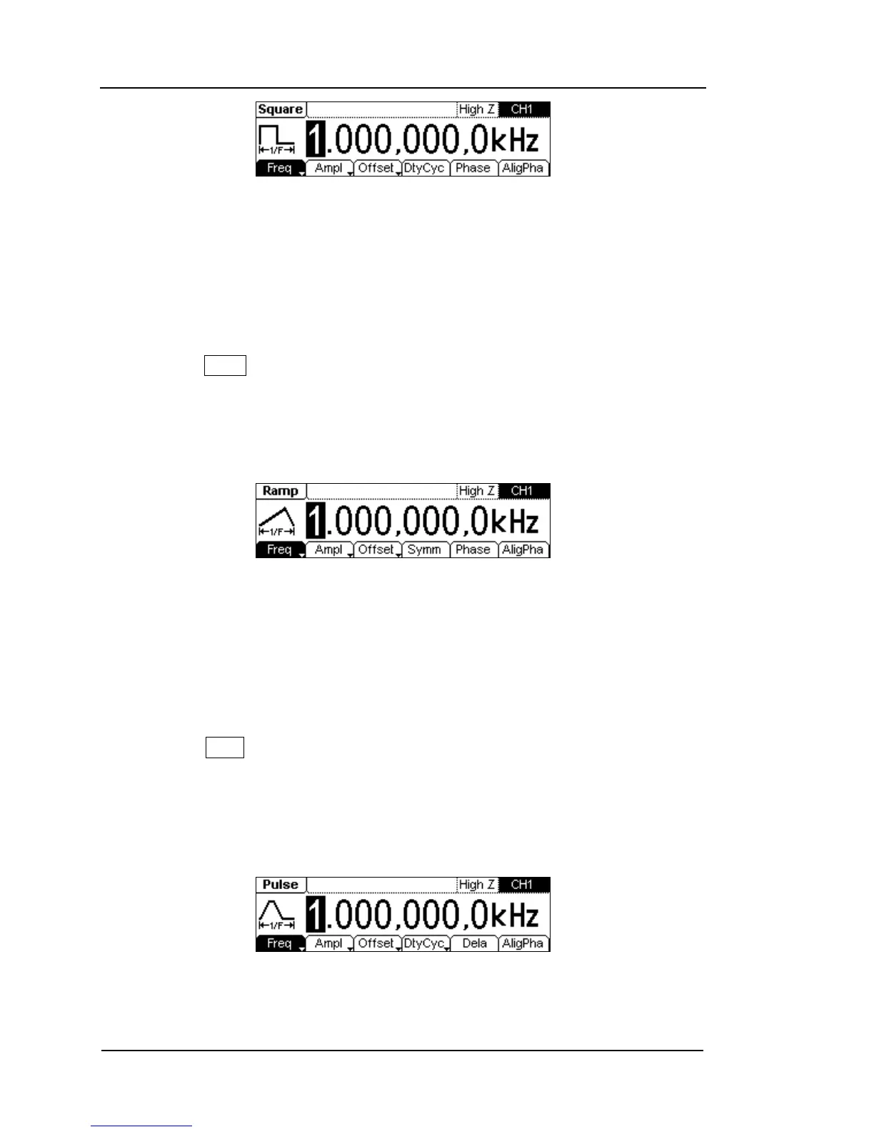
Figure 1-10
Square Signal in the Menu Display Mode
As shown in Figure 1-10, the default signal parameters are: 1kHz Frequency,
5.0VPP Amplitude, 0 VDC Offset, 50% Duty Cycle and 0° initial phase.
3. Press the Ramp button, a “Ramp” typeface will display in the state area. The
instrument can generate Ramp signal with frequency from 1μHz to 150 kHz and
variable Symmetry. By setting
Frequency/Period, Amplitude/ High Level, Offset/
Low level, Symmetry and Phase
, Ramp signal with different parameters can be
generated.
Figure 1-11
Ramp Signal in the Menu Display Mode
As shown in Figure 1-11, the default signal parameters are: 1kHz Frequency, 5.0
VPP Amplitude, 0 VDC Offset, 50% Symmetry and 0° initial phase.
4. Press the Pulse button, a “Pulse” typeface will display in the state area. The
instrument can generate Pulse signal with frequency from 500μHz to 3MHz and
variable Pulse Width. By setting
Frequency/Period, Amplitude/ High Level, Offset/
Low level, Pulse Width/Duty Cycle and Delay
, Pulse signal with different
parameters can be generated.
Figure 1-12
Pulse Signal in the Menu Display Mode