Chapter 7 Protocol Decoding RIGOL
DS4000E User’s Guide 7-3
rising&falling edges ( ) of the clock signal. You can also press Slope
continuously to switch the current edge type.
3. Set the data line
1) Set the bus bits
Press Bus Bits and turn the multi-function knob to set the data width
of the parallel bus (namely the number of bits of each frame of data). The
range is from 1 to 4 and the default is 1 (Bit0).
2) Specify data channel for each bit
First, press CurrentBit and turn the multi-function knob to select the
bit that needs to specify a channel. The range available is from 0 to (the
current bus bits – 1). By default, bit 0 is selected. For example, when the
number of the bus bits is 4, the range available is from 0 to 3.
Then, press Channel, turn the multi-function knob to select the
desired channel and press the knob. You can also press Channel
continuously to switch the channel currently selected. The channels
available include CH1 to CH4.
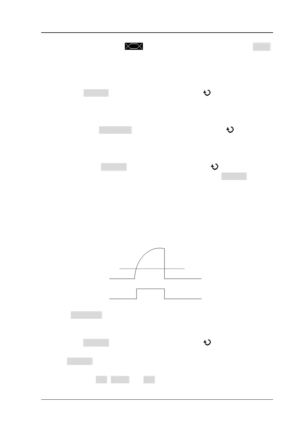
4. Adjust the threshold level
When the channel signal amplitude is greater than the preset threshold, it is
judged as logic “1”; otherwise logic “0”.
Press Threshold to open the threshold setting submenu. In this submenu,
1) Select the specified channel
Press Channel and turn the multi-function knob to select the channel
(CH1 to CH4) that needs to specify the threshold. You can also press
Channel continuously to switch the channel currently selected.
2) Adjust the threshold
Press TTL, COMS and ECL respectively to set the threshold of the
Channel Signal Amplitude
Channel Logic Level
Threshold Level
1
0
0