Chapter 5 Trigger RIGOL
DS4000E User’s Guide 5-35
SPI Trigger
In SPI trigger, if the trigger condition (CS condition or timeout condition) is met, the
oscilloscope will trigger when the specified data is found.
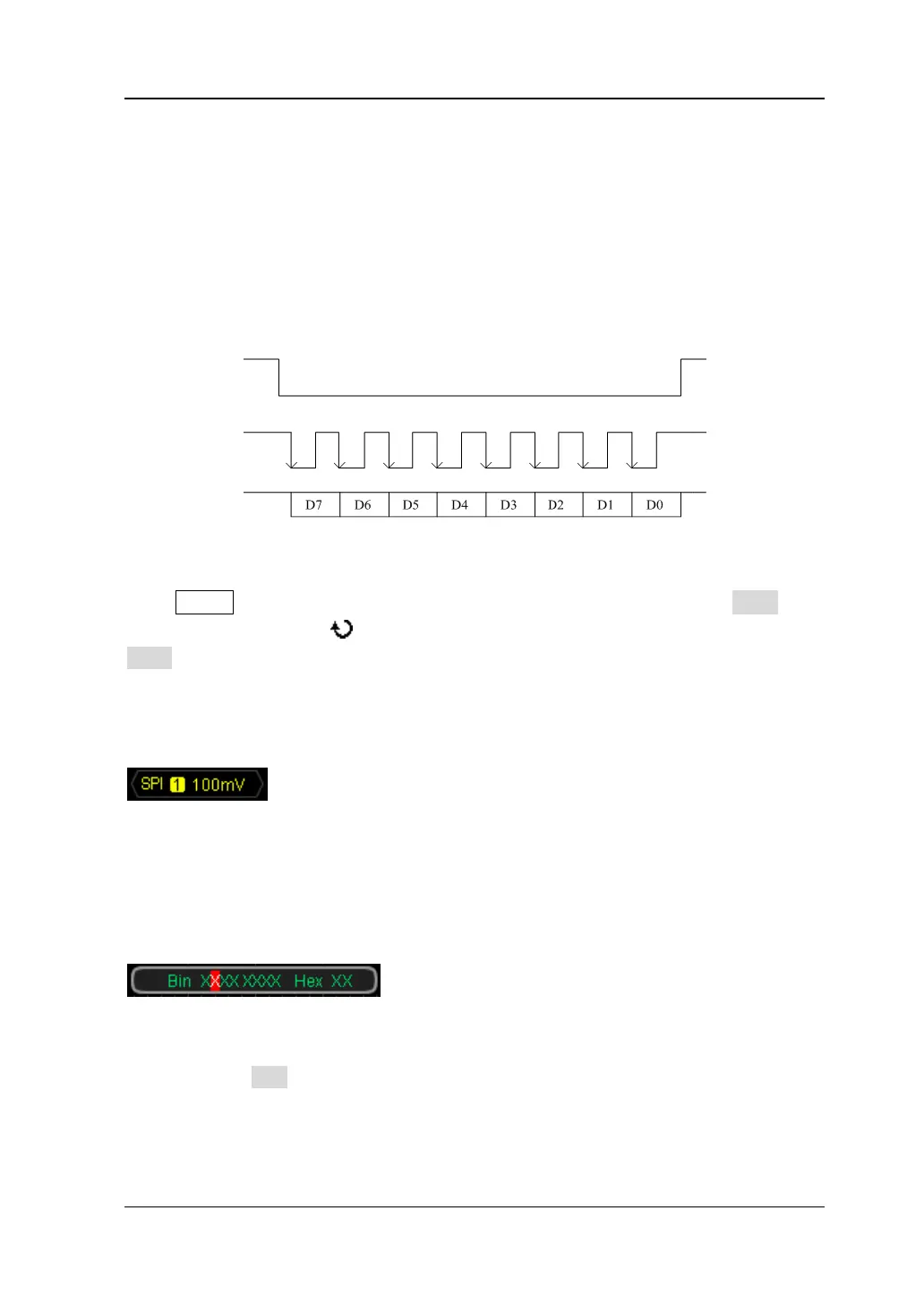
The sequence chart of SPI bus is as shown in the figure below. SCL is the serial clock
line, SDA is the serial data line and CS is the chip select line.
Figure 5-4 SPI Bus Sequence Chart
Press MENU (in the trigger control area (TRIGGER) at the front panel) Type, turn
the multi-function knob to select “SPI” and press the knob. You can also press
Type continuously to switch to “SPI” trigger.
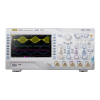
At this point, the trigger setting information (include the trigger type, trigger source
and trigger level, as shown in the figure below) is displayed at the upper-right side of
the screen and changes with the trigger setting.
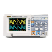
Besides, the data setting area (as shown in the figure below) is displayed at the
bottom of the screen displaying the current data setting information (the data bit
currently selected is highlighted in red) and the data setting information changes
with the data setting.
1. Specify the clock line signal source and adjust the trigger level
Press SCL to select CH1 to CH4 (please refer to “Trigger Source”) as the
channel source of the serial clock line. The signal source currently selected
is displayed at the upper-right side of the screen.
Note: Channels that are turned off can also be selected as the signal
CS
SCL
SDA