Page 48 Doc No. C29115 REV 1
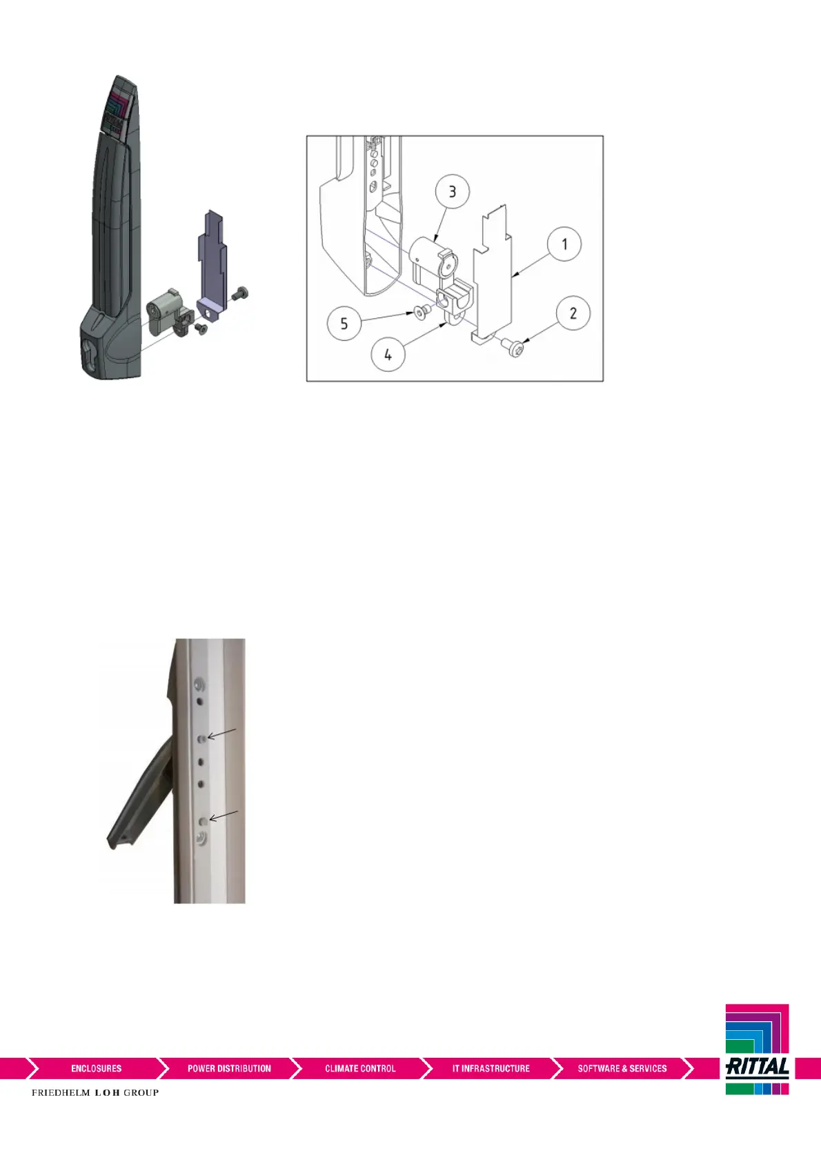
3. Remove cover plate (item 1) and M5x10 screw (item 2) from the back of comfort handle.
4. Remove installed lock insert (item 3) from the adapter (item 4) by removing the M5x8 screw (item 5).
5. Install new lock insert to the adapter (item 4) with M5x8 screw (item 5), as per diagram. Torque: 2(+1)Nm.
6. Fit the lock insert into the aperture in the handle and reinstate cover plate (item 1) and M5x10 screw (item
2). Torque: 2(+1)Nm.
7. Offer handle to door with the handle in the open position, ensure handle pins locate in the correct lock bar
holes as shown, and to allow access for screws.
 Loading...