Installation RMC / RZ / RM / RL
© robatherm 13
Attention
Plan and fit pipework to and from the unit so that the heat exchanger is not subject to
stress and strain e.g. as a result of heavy weights, vibration, tensional forces, heat
expansion etc. Use compensators if necessary.
When tightening the threaded connections of the heat exchanger on site use e.g. a pipe
wrench for counter pressure as the inner pipes may otherwise be twisted and damaged.
Pos: 29.4 /Montage/A nschluss von Wärmeübertr agern_Kältemitte lleitung @ 0\mod_12577 70122341_2008.doc @ 2104 @ 4
The pipes must be flanged in such a way that problem free removal of the heat exchangers
for maintenance or exchange purposes is possible.
Connection of Refrigerating Piping
Prior to connection check the heat exchangers and pipes for leaks, i.e. whether the inert gas
charge on the operation side is still under pressure.
Pos: 30.1 /Montage/_A nschluss der Kondensat- sowie Ab- und Überlauf leitungen @ 0\mod_12577683 04534_2008.doc @ 2090 @ 3
Connection of the Condensate, Discharge and Overflow Piping
Pos: 30.2 /Montage/A nschluss der Kondensat- sowie Ab- und Überlaufl eitungen @ 0\mod_125777029 1293_2008.doc @ 2105 @ 444
Provide all outlets with a siphon (with non-return valve and self-filling device) and remove
waste water appropriately. The height of the siphon must be set in accordance with the low
pressure or overpressure of the ventilation unit so that suction or blowing out of the air in
relation to the connected waste water pipe is prevented.
The water must flow directly from the siphon into a catch pit or funnel. Do not under any
circumstances connect the siphon directly to the sewage network.
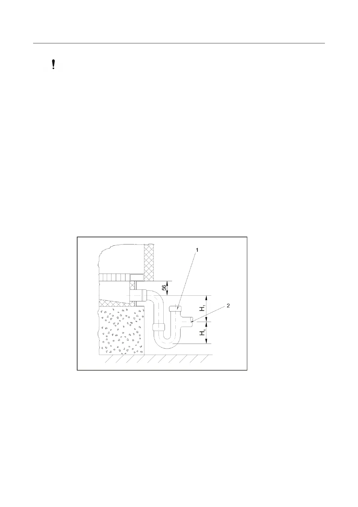
Connection Siphon
1 – Opening for recharge, 2 – Do not connect any horizontal extension
Calculation of Siphon Trap
The height of the siphon is determined as follows:
Under pressure in the device:
H
1
(mm) = p/10
H
S
(mm) = p x 0.075
Overpressure in the device:
H
1
(mm) = 35 mm
H
S
(mm) = (p/10) + 50
p = Unit pressure in Pa (always enter positive value)