11
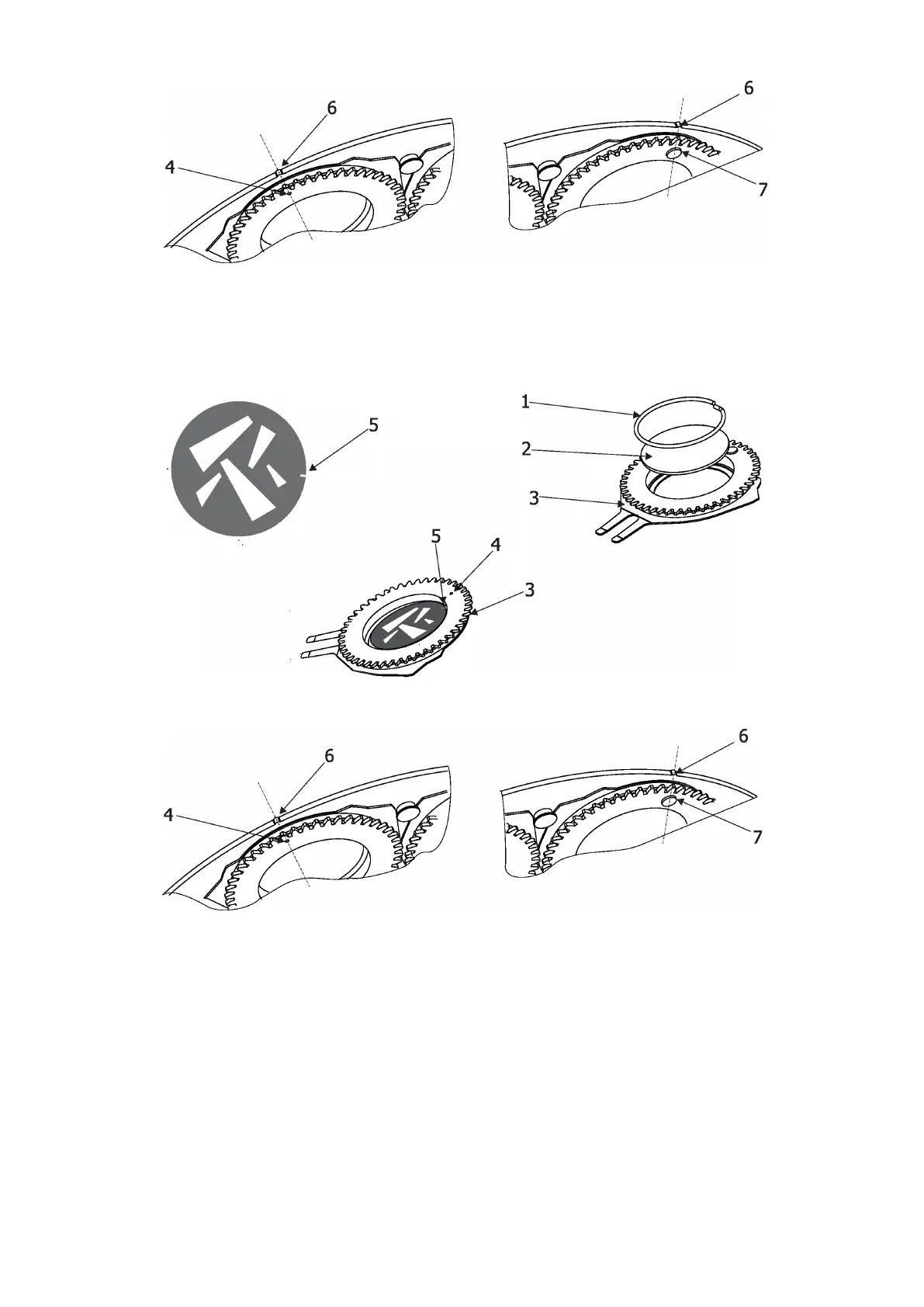
Note: The magnet (7) on the gobo holder substitutes the position point (4).
7
. Gently pull up the gobo holder (3) from the rotation gobo carousel
.
8. Remove the spring lock (1) with an appro
priate tool (e.g. small-bladed screwdriver).
Do not touch the surface of the glass gobo with bare ngers.
9. Remove the original gobo (2) and insert the new one (grey side towards the light source, black side
towards the front lens).
The Robe gobo has a small position point (5) at its edge which has to aim at the position point (4) on
the gobo holder (3). Insert the spring lock (1) to secure correct gobo position in the gobo holder (3).
10. Insert the gobo holder back into gobo carousel in this way, that its position point (4) (or magnet (7) has to
exactly aim at a small toothlike projection (6) on the edge of the rotating gobo wheel. Do not move with
neighbouring gobo holders.
11. Escape the gobo item and enter another gobo item which you want to replace. You do not need to set
the gobo oset again. Repeat steps 5-10 for all gobos which you need to replace on the gobo carousel.
12. After replacing desired gobos, connect the xture to mains and light on changed gobo holders
(or gobos) with max. intensity (shutter/dimmer=255 DMX) approximately 10 minutes per each
changed gobo position to evaporate potential grease from gobo holders and gobos.
During this procedure, the xture head has to be in a horizontal position without top cover (side of xture
head without cover has to be up) and the gobo has to rotate
Note: this step you can leave out if you use original gobo holders from the xture and you sure that new glass
gobos are clean.
13
. Check silica gel d
esiccants
in the xture head before placing head cover back on the xture.
14.
P
lace the head cover back on the xture and screw it by means of the six
h
ex socket head screws M5x16.
Keep required tightening torque as stated in the chapter Maintenance.
Do not forget to connect grounding wire between chassis and head cover.
15. Run the procedure Pressure Test (tab Service -->Pressure Test).