8
3.1 Connection to the mains
To apply power, rst check that the head pan and tilt locks are released.
For protection from electric shock, the xture must be earthed!
The xture has to be connected to an electric outlet which is equipped with
a residual-current device (residual-current circuit breaker)!
Wiring and connection work must be carried out by a qualied electrician.
The Robin iForte is equipped with auto-switching power supply that automatically adjusts to any 50-60Hz AC
power source from 100-240 Volts.
Mains cable powerCON TRUE1 In/open ended is enclosed to the xture. We recomend to install cord end-
sleeves 1.5 x 8 (cross section in mm
2
x length in mm) on the cords of the mains cable. If you need to install a
power plug on the mains cable to allow connection to power outlets, install a grounding-type (earthed) plug,
following the plug manufacturer’s instructions. If you have any doubts about proper installation, consult a qual-
ied electrician. Connection to mains has to keep IP 65 protection rating.
Core (EU) Core (US) Connection Plug Terminal Marking
Brown Black Live L
Light blue White Neutral N
Yellow/Green Green Earth PE/GND
This device falls under class one and must be earthed (grounded).
Ensure all connections and the power plug on the cable are properly sealed.
3.2 Replacing the frosts
Unplug the xture from mains before replacing frost!
Do not replace frost in a damp environment (e.g. rain, snowfall)!
Do not remove xture covers in smoky or particularly dirty
environment (e.g. with fog machines)
o replace the frost.
1. Disconnect the xture from mains and allow it to cool for 60 minutes.
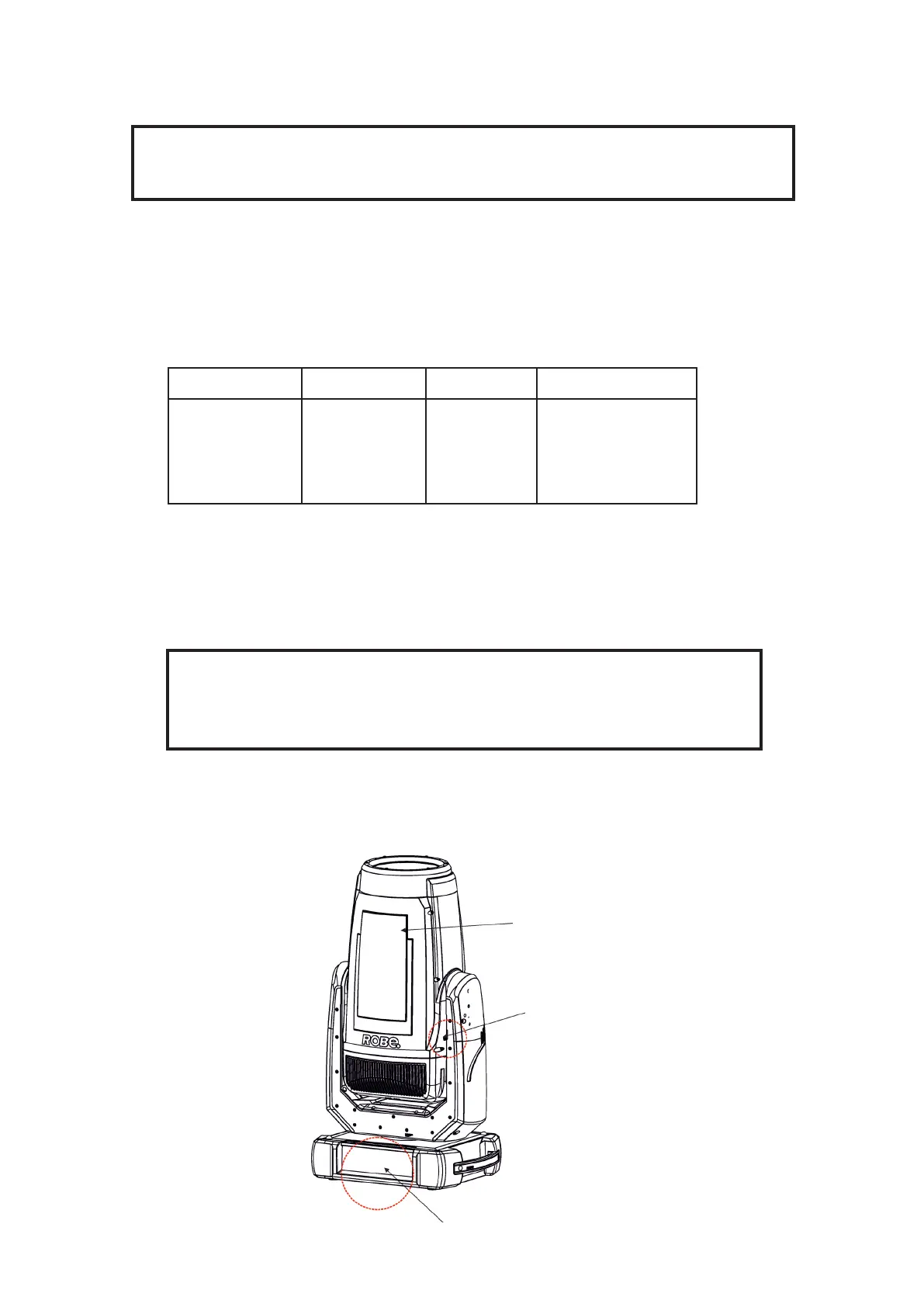
2. Move the xture head to the position as shown on the picture below (the tilt lock has to be on the same side
as the display) to determine which top cover of the head has to be removed. Remove the top cover of the head
by unscrewing 6
h
ex socket head screws M5x16 on the cover to get access to the 1° frost (1) and 5° frost (7).
Display
Top cover
Tilt lock