Rockwell Automation Publication 843ES-UM001A-EN-P - February 2020 31
Installation Chapter 3
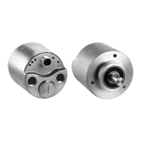
For the hollow shaft encoders, the coupling elements, such as a stator coupling or
a compensating torque stop, are supplied mounted.
Screws and Screwed Connections
Unless otherwise specified, a friction coefficient of 0.14 is assumed for all screwed
connections.
Unless otherwise specified, a strength class of 8.8 is assumed for all screws. The
screws must be secured against loosening by using one of the following:
•Coated screws
• Threadlocker, example Loctite®
•SCHNORR® washers
We recommend an additional protection against manipulation by marking the
fastening screws such as with locking varnish.
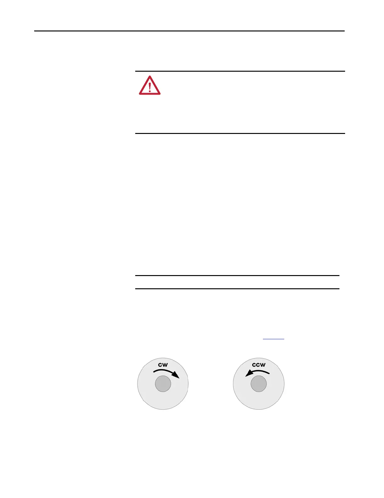
Shaft Rotation Direction
When you view the encoder from the shaft side, the shaft rotation is clockwise
(CW) or counterclockwise (CCW), as shown in Figure 3
.
Figure 3 - Shaft Rotation
ATTENTION: IEC 61800-5-2 defines the loosening of mechanical connection
(between the encoder and the drive) as a fault that requires consideration. Fault
exclusion is required for the coupling elements if the control cannot detect this
fault. Therefore, design the coupling between the encoder and apparatus for
fault exclusion so that any possibility of breakage at the coupling can be ruled
out. To achieve this fault exclusion, the encoder mechanical limits and
mounting practices in this document must be considered.
IMPORTANT For assembly, use only checked and calibrated tools.
 Loading...