34 Rockwell Automation Publication 843ES-UM001A-EN-P - February 2020
Chapter 3 Installation
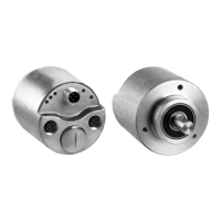
Mount with a Hollow Shaft
For hollow shaft encoders, the coupling elements (for example, a stator coupling
or a compensating torque stop) are factory-mounted.
1. Check the shafts for offset. The maximum allowed shaft connection
tolerances are:
• Axial offset < ±0.25 mm (0.01 in.)
• Radial offset < ±0.20 mm (0.008 in.)
2. Slide the encoder onto the mating shaft until the flex mount rests on the
machine surface. Minimum insertion depth for hollow shaft is 25.5 mm
(1.0 in.).
3. Hold encoder firmly and mark the two mounting holes. To determine the
encoder mounting hole locations, see Hollow Shaft Approximate
Dimensions. (If mounting holes exist, proceed to step 6.)
4. Slide the encoder off. To accept M3 (or equivalent) screws, drill and tap
the marked holes.
5. Slide the encoder back onto the shaft until the flex mount rests on the
machine surface.
6. Attach the encoder with two M3 (or equivalent) screws. Screw the stator
coupling and the torque stop without preload on the drive flange. Tighten
the screws to 1 N•m [8.9 lb•in].
7. Tighten the clamping ring screw to 2.5 N•m (22.1 lb•in).
8. Align machine to its mechanical zero or home position.
IMPORTANT • Verify that the insertion depth of the load shaft into the hollow shaft
encoder is ≥25.5 mm (1.0 in.)
• Verify that the mating shaft is chamfered and grease-free.
ATTENTION: The encoder slides freely onto the shaft; if not, do not force.
Check the shaft for interferences such as gouges, burrs, rust, or size.
IMPORTANT Do not stress the flex mount while tightening the screws.
 Loading...