Rockwell Automation Publication 843ES-UM001A-EN-P - February 2020 73
Chapter 6
Diagnostics and Troubleshooting
This chapter describes the diagnostic process to correct and clear fault conditions
on the 843ES CIP Safety encoder.
After switching on the power supply, wait at least 10 seconds until the encoder is
ready for operation and interfaces are ready for communication. The encoder
communicates with the digital interface after this period of time.
Status Indicators
The Mod status indicator shows the device status. The Net status indicator shows
the status of the CIP connection. The Encoder status indicator shows the status
of the internal measuring device in the 843ES CIP Safety encoder.
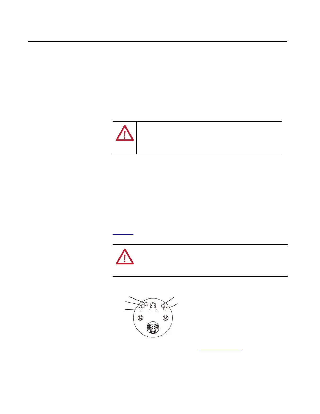
Four status indicators provide status information on the back of the encoder.
Figure 14
shows their location and the tables describe their status.
Figure 14 - Status Indicator Location
Read the status indicators according to Table 23 on page 74.
ATTENTION: Cease operation if the cause of the malfunction has not been
identified.
Stop the machine if you cannot clearly identify the error and/or if you cannot
safely rectify the malfunction.
ATTENTION: Status indicators are not reliable indicators and cannot be
guaranteed to provide accurate information. They should only be used for
general diagnostics during commissioning or troubleshooting. Do not attempt
to use status indicators as operational indicators.
GND
10…30V DC
Port 1 Port 2
Net
Mod
Link 1
Encoder (not used)
Link 2
 Loading...