Rockwell Automation Publication 843ES-UM001A-EN-P - February 2020 35
Installation Chapter 3
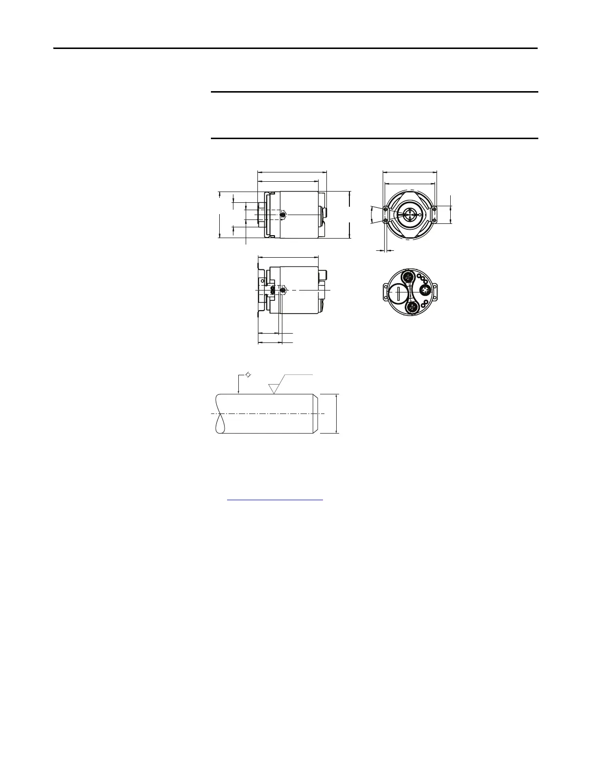
Hollow Shaft Approximate Dimensions
Figure 7 - Hollow Shaft 63 mm (2.5 in.) Diameter [mm (in.)]
Figure 8 - Application Side Requirements for Hollow Shaft Encoders
Mechanical Specifications
See Appendix A on page 79.
IMPORTANT To simplify the drawings and information, unless otherwise specified, the
general tolerances with tolerance class m (medium) according to ISO 2768-1
apply.
ØD h7
76 (2.99)
86.5 (3.41)
Ø59
(2.32)
Ø58
(2.28)
31
(1.22)
25°
22
(0.87)
Ø3.2 (0.13)
68 (2.68)
Ø63 (2.48)
30 (1.18) max
Insertion 25.5 (1) max
75.5 (2.97)
0.1
Ra 1.6
ø X
f6
(Rec. ø X
g6
)
Material: Stainless steel
 Loading...