32 Rockwell Automation Publication 843ES-UM001A-EN-P - February 2020
Chapter 3 Installation
Mount with a Solid Shaft
1. Be sure to select the proper size flexible coupling clamp to mate to the
encoder shaft. See publication 847-TD001
for encoder accessories.
2. To determine the encoder mounting hole locations, see Solid Shaft
Approximate Dimensions on page 32.
3. Fasten the encoder and tighten with three size M3 mounting screws
(provided with the flange).
4. Tighten the screws at a torque of 1 N•m (8.9 lb•in) and secure them
against loosening.
5. Check the shafts for offset. The maximum permissible tolerances depend
on the selected shaft coupling.
6. Connect the encoder and load shaft with a flexible coupling.
7. During assembly, protect the coupling element against excessive bending
and damage.
8. Center the flexible coupling, screw the coupling without pre-load, and
secure it against loosening.
9. Rotate the machine slowly and verify that the flexible coupling is not
deforming beyond specifications.
10. Align machine to its mechanical zero or home position.
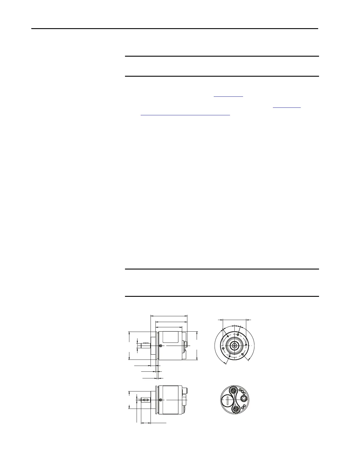
Solid Shaft Approximate Dimensions
Figure 4 - Solid Shaft with Clamping Flange [mm (in.)]
IMPORTANT For solid shaft encoders, a suitable shaft coupling that meets the requirements
of the application must be used.
IMPORTANT To simplify the drawings and information, unless otherwise specified, the
general tolerances with tolerance class m (medium) according to ISO 2768-1
apply.
75.5 (2.97)
55 (2.17)
65.5 (2.58)
10 (0.39)
3 (0.12)
3 (0.12)
Ø59
(2.32)
Ø58
(2.28)
Ø48 (1.89)
35°
17°
3 x 120°
3 x 120°
20 (0.79)
3
(0.12 )
N9
N9
Ø36
(1.42)
ØD f7
22.225 (0.875) - 3/8 in. shaft
 Loading...