114 Rockwell Automation Publication 20D-PM001D-EN-P - March 2019
Chapter 2 Programming and Parameters
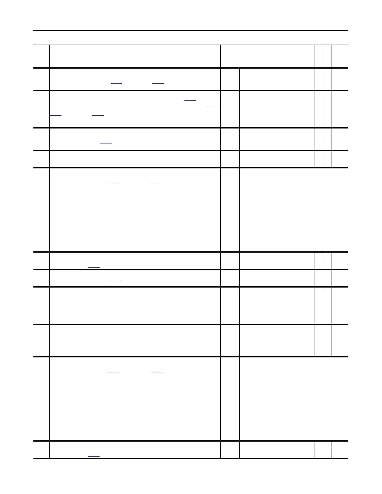
841 Anlg Out2 Offset
Provides an offset for Analog Output 2 before the scaling and limit blocks in the Analog Output 2 function. This
parameter value is summed with either Par
839 [Anlg Out2 DInt] or Par 840 [Anlg Out2 Real] at the beginning of
the function.
Default:
Min/Max:
0.0000
-/+2200000000.0000
Y
RW Real
842 Anlg Out2 Scale
Scales the range of the source parameter to the range of Analog Output 2. For example: If Par 838 [Anlg Out2 Sel]
is set to 1 “Output Freq”, the output frequency of the drive is 0 - 60Hz and you enter “6” in this parameter, Par
844
[Anlg Out2 Value] = 6Hz per 1V, or 0 - 60Hz.
Par 839 [Anlg Out2 DInt] or Par 840 [Anlg Out2 Real] is multiplied by this number after the limit function.
Note: The turn-off point for this parameter has been changed from ±0.001 to ±0.0001 for firmware version
4.002.
Default:
Min/Max:
Units:
0.0000
-/+2200000000.0000
/V
Y
RW Real
843 Anlg Out2 Zero
Applies an offset to the scaled value of Analog Output 2. This parameter is summed with the output of the
scaling block. This sum produces Par
844 [Anlg Out2 Value]. Typically this value corresponds to 0V for Analog
Output 2.
Default:
Min/Max:
Units:
0.0000
-/+20.0000
V
Y
RW Real
844 Anlg Out2 Value
Displays the voltage reference for Analog Output 2 before the digital to analog conversion.
Default:
Min/Max:
Units:
0.0000
-/+10.0000
V
RO Real
845 Dig Out1 Sel
identifies the signal used on Digital Output 1. If the desired signal is not available in the selection list, choose
option 0 - “User Select” and link with Par 846 [Dig Out1 Data] and Par 847 [Dig Out1 Bit] to select the desired
parameter and bit for output.
Default:
Options:
3 =
0 =
1 =
2 =
3 =
4 =
5 =
6 =
7 =
8 =
9 =
10 =
11 =
12 =
13 =
14 =
“Ready”
“User Select” 15 = “Torque Limit”
“Not Fault” 16 = “Power Limit”
“Not Alarm” 17 = “Fault”
“Ready” 18 = “Alarm”
“Running” 19 = “Command Dir”
“Reserved” 20 = “Actual Dir”
“Reserved” 21 = “Jogging”
“Enable On” 22 = “In Position”
“Active” 23 = “Posit Watch1”
“At Speed” 24 = “Posit Watch2”
“At Setpt 1” 25 = “Cmpr 1 A</=B”
“Above Setpt 2” 26 = “Cmpr 1 A>/=B”
“At ZeroSpeed” 27 = “Cmpr 2 A</=B”
“Speed Limit” 28 = “Cmpr 2 A>/=B”
“CurrentLimit”
846 Dig Out1 Data
Link a word to this parameter that will control Digital Output 1. The bit within the selected word that will control
Digital Output 1 is set by Par
847 [Dig Out1 Bit].
Default:
Min:
Max:
00000000000000000000000000000000
00000000000000000000000000000000
11111111111111111111111111111111
Y
RW 32-bit
Boolean
847 Dig Out1 Bit
Selects the bit, from the word linked to Par 846 [Dig Out1 Data], that will change the status of Digital Output 1
(e.g., when Par 847 [Dig Out1 Bit] equals 0, bit 0 of Par 846 [Dig Out1 Data] will control Digital Output 1).
Default:
Min/Max:
0
-32/31
Y
RW 16-bit
Integer
848 Dig Out1 On Time
Defines the amount of time between a False to True transition on the output status and the corresponding
change in state of Digital Output 1. If a transition on an output condition occurs and starts the time delay and the
output condition returns to its original state before the delay timer reaches the setpoint, the delay timer will be
aborted and the corresponding output status or digital output will not change state. Par 848 [Dig Out1 On Time]
can be disabled by setting the delay time to 0 (zero).
Note: This parameter was added for firmware version 3.001.
Default:
Min/Max:
Units:
0.00
0.00/600.00
s
RW 16-bit
Integer
849 Dig Out1 OffTime
Defines the amount of time between a True to False transition on the output status and the corresponding
change in state of Digital Output 1. If a transition on an output condition occurs and starts the time delay and the
output condition returns to its original state before the delay timer reaches the setpoint, the delay timer will be
aborted and the corresponding output status or digital output will not change state.
Note: This parameter was added for firmware version 3.001.
Default:
Min/Max:
Units:
0.00
0.00/600.00
s
RW 16-bit
Integer
850 Dig Out2 Sel
Identifies the signal used on Digital Output 2. If the desired signal is not available in the selection list, choose
option 0 - “User Select” and link with Par
851 [Dig Out 2 Data] and Par 852 [Dig Out2 Bit] to select the desired
parameter and bit for output.
Default:
Options:
8 =
0 =
1 =
2 =
3 =
4 =
5 =
6 =
7 =
8 =
9 =
10 =
11 =
12 =
13 =
14 =
“Ac ti ve”
“User Select” 15 = “Torque Limit”
“Not Fault” 16 = “Power Limit”
“Not Alarm” 17 = “Fault”
“Ready” 18 = “Alarm”
“Running” 19 = “Command Dir”
“Reserved” 20 = “Actual Dir”
“Reserved” 21 = “Jogging”
“Enable On” 22 = “In Position”
“Active” 23 = “Posit Watch1”
“At Speed” 24 = “Posit Watch2”
“At Setpt 1” 25 = “Cmpr 1 A</=B”
“Above Setpt 2” 26 = “Cmpr 1 A>/=B”
“At ZeroSpeed” 27 = “Cmpr 2 A</=B”
“Speed Limit” 28 = “Cmpr 2 A>/=B”
“CurrentLimit”
851 Dig Out2 Data
Link a word to this parameter that will control Digital Output 2. The bit within the selected word that will control
Digital Output 2 is set by Par
852 [Dig Out2 Bit].
Default:
Min:
Max:
00000000000000000000000000000000
00000000000000000000000000000000
11111111111111111111111111111111
Y
RW 32-bit
Boolean
No. Name
Description
Values
Linkable
Read-Write
Data Type
 Loading...


