Rockwell Automation Publication 20D-PM001D-EN-P - March 2019 113
Programming and Parameters Chapter 2
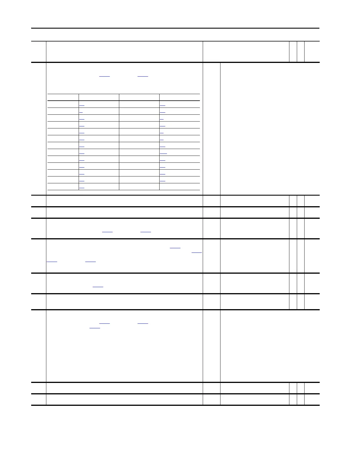
831 Anlg Out1 Sel
Identifies the signal used on Analog Output 1. If the desired signal is not available in the selection list, choose
option 0 - “User Select” and link with Par
832 [Anlg Out1 DInt] or Par 833 [Anlg Out1 Real] to select the desired
parameter for output.
The following table provides the parameter that corresponds to the option selected in this parameter.
Default:
Options:
17 =
0 =
1 =
2 =
3 =
4 =
5 =
6 =
7 =
8 =
9 =
10 =
11 =
12 =
13 =
“Speed Fdbk”
“User Select” 14 = “Reserved”
“Output Freq” 15 = “Motor TrqRef”
“Sel Spd Ref” 16 = “MtrTrqCurRef”
“Output Curr” 17 = “Speed Ref”
“Trq Cur (Iq)” 18 = “Speed Fdbk”
“% Motor Flux” 19 = “Torque Est”
“Output Power” 20 = “Scl Spd Fdbk”
“Output Volts” 21 = “RampedSpdRef”
“DC Bus Volts” 22 = “Spd Reg Out”
“PI Reference” 23 = “MOP Level”
“PI Feedback” 24 = “Trend 1 DInt”
“PI Error” 25 = “Trend 1 Real”
“PI Output” 26 = “Trend 2 DInt”
“Reserved” 27 = “Trend 2 Real”
832 Anlg Out1 DInt
Link this parameter to an integer source parameter that will control Analog Output 1.
Default:
Min/Max:
0
-/+2147483648
Y
RW 32-bit
Integer
833 Anlg Out1 Real
Link this parameter to a real (floating point) source parameter that will control Analog Output 1.
Default:
Min/Max:
0.0000
-/+2200000000.0000.0000
Y
RW Real
834 Anlg Out1 Offset
Provides an offset for Analog Output 1 before the scaling and limit blocks in the Analog Output 1 function. This
parameter value is summed with either Par 832 [Anlg Out1 DInt] or Par 833 [Anlg Out1 Real] at the beginning of
the function.
Default:
Min/Max:
0.0000
-/+2200000000.0000
Y
RW Real
835 Anlg Out1 Scale
Scales the range of the source parameter to the range of Analog Output 1. For example: If Par 831 [Anlg Out1 Sel]
is set to 1 “Output Freq”, the output frequency of the drive is 0 - 60Hz and you enter “6” in this parameter, Par 837
[Anlg Out1 Value] = 6Hz per 1V, or 0 - 60Hz.
Par
832 [Anlg Out1 DInt] or Par 833 [Anlg Out1 Real] is multiplied by this number after the limit function.
Note: The turn-off point for this parameter has been changed from ±0.001 to ±0.0001 for firmware version
4.002.
Default:
Min/Max:
Units:
0.0000
-/+2200000000.0000
/V
Y
RW Real
836 Anlg Out1 Zero
Applies an offset to the scaled value of Analog Output 1. This parameter is summed with the output of the
scaling block. This sum produces Par
837 [Anlg Out1 Value]. Typically this value corresponds to 0V for Analog
Output 1.
Default:
Min/Max:
Units:
0.0000
-/+20.0000
V
Y
RW Real
837 Anlg Out1 Value
Displays the voltage reference for Analog Output 1 before the digital to analog conversion.
Default:
Min/Max:
Units:
0.0000
-/+10.0000
V
RO Real
838 Anlg Out2 Sel
Identifies the signal used on Analog Output 2. If the desired signal is not available in the selection list, choose
option 0 - “User Select” and link with Par 839 [Anlg Out2 DInt] or Par 840 [Anlg Out2 Real] to select the desired
parameter for output. Refer to Par
831 for a list of parameters that correspond to the option selected in this
parameter.
Default:
Options:
3 =
0 =
1 =
2 =
3 =
4 =
5 =
6 =
7 =
8 =
9 =
10 =
11 =
12 =
13 =
“Output Curr”
“User Select” 14 = “Reserved”
“Output Freq” 15 = “Motor TrqRef”
“Sel Spd Ref” 16 = “MtrTrqCurRef”
“Output Curr” 17 = “Speed Ref”
“Trq Cur (Iq)” 18 = “Speed Fdbk”
“% Motor Flux” 19 = “Torque Est”
“Output Power” 20 = “Scl Spd Fdbk”
“Output Volts” 21 = “RampedSpdRef”
“DC Bus Volts” 22 = “Spd Reg Out”
“PI Reference” 23 = “MOP Level”
“PI Feedback” 24 = “Trend 1 DInt”
“PI Error” 25 = “Trend 1 Real”
“PI Output” 26 = “Trend 2 DInt”
“Reserved” 27 = “Trend 2 Real”
839 Anlg Out2 DInt
Link this parameter to an integer source parameter that will control Analog Output 2.
Default:
Min/Max:
0
-/+2147483648
Y
RW 32-bit
Integer
840 Anlg Out2 Real
Link this parameter to a real (floating point) source parameter that will control Analog Output 2.
Default:
Min/Max:
0.0000
-/+2200000000.0000
Y
RW Real
No. Name
Description
Values
Linkable
Read-Write
Data Type
Option Parameter Option Parameter
1 “Output Freq” 310
[Output Freq] 16 “MtrTrqCurRef” 305 [Mtr Trq Curr Ref]
2 “Sel Spd Ref” 40
[Selected Spd Ref] 17 “Speed Ref” 301 [Motor Speed Ref]
3 “Output Curr” 308
[Output Current] 18 “Speed Fdbk” 71 [Filtered SpdFdbk]
4 “Trq Cur (Iq)” 499
[Trq Cur Fdbk (Iq)] 19 “Torque Est” 471 [Estimated Torque]
5 “% Motor Flux” 309
[% Motor Flux] 20 “Scl Spd Fdbk” 72 [Scaled Spd Fdbk]
6 “Output Power” 311
[Output Power] 21 “RampedSpdRef” 43 [Ramped Spd Ref]
7 “Output Volts” 307
[Output Voltage] 22 “Spd Reg Out” 101 [SpdReg Integ Out]
8 “DC Bus Volts” 306
[DC Bus Voltage] 23 “MOP Level” 1090 [MOP Level Real]
9 “PI Reference” 181
[PI Reference] 24 “Trend 1 DInt” 572 [Trend Out1 DInt]
10 “PI Feedback” 182
[PI Feedback] 25 “Trend 1 Real” 573 [Trend Out1 Real]
11 “PI Error” 183
[PI Error] 26 “Trend 2 DInt” 576 [Trend Out2 DInt]
12 “PI Output” 180
[PI Output] 27 “Trend 2 Real” 577 [Trend Out2 Real]
15 “Motor TrqRef” 303
[Motor Torque Ref]
 Loading...


