112 Rockwell Automation Publication 20D-PM001D-EN-P - March 2019
Chapter 2 Programming and Parameters
825 Dig In1 Sel
Enter a value to select the function of digital input 1.
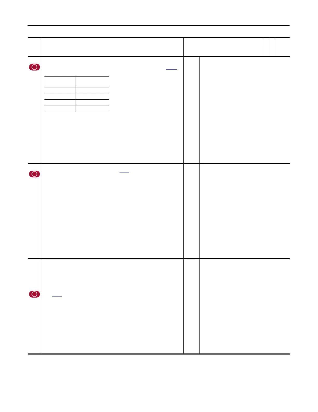
Selecting options 34 “UserGen Sel0” - 37 “UserGen Sel3” sends Binary Coded Decimal (BCD) data to Par
1022 [Sel
Switch Ctrl] as follows:
Note: For all Stop Functions: Low = Stop, High = OK to Run, In "Norm Stop-CF" Low = Normal Stop and
Clear Fault.
Note: When Using the MAH instruction in DriveLogix to “home” an axis and Digital Input 1 is used as the
homing switch, this parameter must be set to 0 “Not Used”. When the MAH instruction is executed,
this parameter will be changed to option 31 “Regis 1 Ltch”, to indicate that the drive registration has
latched the encoder position when the switch was activated.
Note: Option 38 “ExtFault Inv” was added for firmware version 2.004. Option 39 “Home Switch” was added
for firmware version 3.001. Values 41 and 42 were added for firmware version 4.001.
Note: Option 20 “Accel Decel2” is not functional.
Default:
Options:
0 =
0 =
1 =
2 =
3 =
4 =
5 =
6 =
7 =
8 =
9 =
10 =
11 =
12 =
13 =
14 =
15 =
16 =
17 =
18 =
19 =
20 =
“Not Used”
“Not Used” 21 = “Indx Step”
“Enable” 22 = “Indx StepRev”
“Clear Faults” 23 = “MOP Inc”
“Ext Fault” 24 = “MOP Dec”
“Norm Stop-CF” 25 = “MOP Reset”
“Start” 26 = “PI Trim En”
“Reverse” 27 = “PI Trim Hold”
“Run” 28 = “PI Trim Rst”
“Reserved” 29 = “Trend Trig”
“Reserved” 30 = “PreCharge En”
“Jog 1” 31 = “Regis 1 Ltch”
“Reserved” 32 = “+Hrd OvrTrvl”
“Reserved” 33 = “-Hrd OvrTrvl”
“Jog 2” 34 = “UserGen Sel0”
“Normal Stop” 35 = “UserGen Sel1”
“Spd Ref Sel0” 36 = “UserGen Sel2”
“Spd Ref Sel1” 37 = “UserGen Sel3”
“Spd Ref Sel2” 38 = “ExtFault Inv”
“CurLim Stop” 39 = “Home Switch”
“Coast Stop” 41 = “Find Home”
“Accel Decel2” 42 = “Return Home”
826 Dig In2 Sel
Enter a value to select the function of digital input 2. Refer to Par 825 for a description of options 34 “UserGen
Sel0” - 37 “UserGen Sel3”.
Note: For all Stop Functions: Low = Stop, High = OK to Run, In "Norm Stop-CF" Low = Normal Stop and
Clear Fault.
Note: Notes:Option 38 “ExtFault Inv” was added for firmware version 2.004. Option 39 “Home Switch” was
added for firmware version 3.001. Values 41 and 42 were added for firmware version 4.001.
Default:
Options:
0 =
0 =
1 =
2 =
3 =
4 =
5 =
6 =
7 =
8 =
9 =
10 =
11 =
12 =
13 =
14 =
15 =
16 =
17 =
18 =
19 =
20 =
“Not Used”
“Not Used” 21 = “Indx Step”
“Enable” 22 = “Indx StepRev”
“Clear Faults” 23 = “MOP Inc”
“Ext Fault” 24 = “MOP Dec”
“Norm Stop-CF” 25 = “MOP Reset”
“Start” 26 = “PI Trim En”
“Reverse” 27 = “PI Trim Hold”
“Run” 28 = “PI Trim Rst”
“Reserved” 29 = “Trend Trig”
“Reserved” 30 = “PreCharge En”
“Jog 1” 31 = “Regis 2 Ltch”
“Reserved” 32 = “+Hrd OvrTrvl”
“Reserved” 33 = “-Hrd OvrTrvl”
“Jog 2” 34 = “UserGen Sel0”
“Normal Stop” 35 = “UserGen Sel1”
“Spd Ref Sel0” 36 = “UserGen Sel2”
“Spd Ref Sel1” 37 = “UserGen Sel3”
“Spd Ref Sel2” 38 = “ExtFault Inv”
“CurLim Stop” 39 = “Home Switch”
“Coast Stop” 41 = “Find Home”
“Accel Decel2” 42 = “Return Home”
827
828
829
830
Dig In3 Sel
Enter a value to select the function of digital input 3.
Dig In4 Sel
Enter a value to select the function of digital input 4.
Dig In5 Sel
Enter a value to select the function of digital input 5.
Dig In6 Sel
Enter a value to select the function of digital input 6.
Refer to Par
825 for a description of options 34 “UserGen Sel0” - 37 “UserGen Sel3”.
Note: For all Stop Functions: Low = Stop, High = OK to Run, In "Norm Stop-CF" Low = Normal Stop and
Clear Fault.
Note: Notes: Option 38 “ExtFault Inv” was added for firmware version 2.004. Option 39 “Home Switch” was
added for firmware version 3.001. Values 41 and 42 were added and value 39 was deleted for
firmware version 4.001.
Note:
(1)
Opening an “Enable” input will cause the motor to coast-to-stop, ignoring any programmed Stop
modes.
Default:
Options:
0 =
0 =
1 =
2 =
3 =
4 =
5 =
6 =
7 =
8 =
9 =
10 =
11 =
12 =
13 =
14 =
15 =
16 =
17 =
18 =
19 =
20 =
“Not Used”
“Not Used” 21 = “Indx Step”
“Enable”
(1)
22 = “Indx StepRev”
“Clear Faults” 23 = “MOP Inc”
“Ext Fault” 24 = “MOP Dec”
“Norm Stop-CF” 25 = “MOP Reset”
“Start” 26 = “PI Trim En”
“Reverse” 27 = “PI Trim Hold”
“Run” 28 = “PI Trim Rst”
“Reserved” 29 = “Trend Trig”
“Reserved” 30 = “PreCharge En”
“Jog 1” 31 = “Reserved”
“Reserved” 32 = “+Hrd OvrTrvl”
“Reserved” 33 = “-Hrd OvrTrvl”
“Jog 2” 34 = “UserGen Sel0”
“Normal Stop” 35 = “UserGen Sel1”
“Spd Ref Sel0” 36 = “UserGen Sel2”
“Spd Ref Sel1” 37 = “UserGen Sel3”
“Spd Ref Sel2” 38 = “ExtFault Inv”
“CurLim Stop” 39 = “Reserved”
“Coast Stop” 41 = “Find Home”
“Accel Decel2” 42 = “Return Home”
No. Name
Description
Values
Linkable
Read-Write
Data Type
Selection Sends Input to this bit
in Par 1022
34 “UserGen Sel0” Bit 1 “Sel Switch 00”
35 “UserGen Sel1” Bit 2 “Sel Switch 01”
36 “UserGen Sel2” Bit 3 “Sel Switch 02”
37 “UserGen Sel3” Bit 4 “Sel Switch 03”
 Loading...


