116 Rockwell Automation Publication 20D-PM001D-EN-P - March 2019
Chapter 2 Programming and Parameters
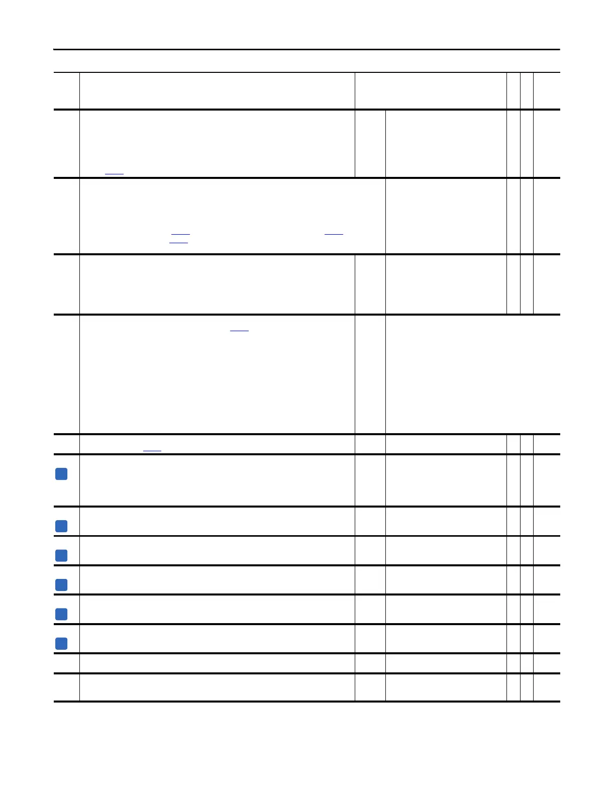
862
867
872
877
882
887
BitSwap 1B Data
BitSwap 2B Data
BitSwap 3B Data
BitSwap 4B Data
BitSwap 5B Data
BitSwap 6B Data
This parameter contains the word from which the replacement bit will be selected. Only the selected bit is
passed to Par
864 [BitSwap 1 Result].
Default:
Min/Max:
0
32 bits of data
Y
RW 32-bit
Boolean
863
868
873
878
883
888
BitSwap 1B Bit
BitSwap 2B Bit
BitSwap 3B Bit
BitSwap 4B Bit
BitSwap 5B Bit
BitSwap 6B Bit
This parameter specifies the bit from Par 862 [BitSwap 1B Data] that will replace the specified bit in Par 860
[BitSwap 1A Data] and be loaded to Par
864 [BitSwap 1 Result]. A negative bit selection may be used to invert
the data. Use “-32” to invert the value of bit 0.
Default:
Min/Max:
0
-32/+31
RW 16-bit
Integer
864
869
874
879
884
889
BitSwap 1 Result
BitSwap 2 Result
BitSwap 3 Result
BitSwap 4 Result
BitSwap 5 Result
BitSwap 6 Result
This parameter contains the result of the Bit Swap operation.
Default:
Min/Max:
0
32 bits of data
RO 32-bit
Boolean
892 SL Comm TP Sel
Enter or write a value to select SynchLink™ data displayed by Par 893 [SL Comm TP Data].
Default:
Options:
0 =
0 =
1 =
2 =
3 =
4 =
5 =
6 =
7 =
8 =
9 =
10 =
11 =
12 =
“Zero”
“Zero” 13 = “BufSeqErrTim”
“SL MultA Src” 14 = “Rx Sys Rev”
“SL Mult A In” 15 = “Tx Axis Size”
“SL Mult B In” 16 = “Tx Dir Size”
“SL Mult Out” 17 = “Tx Buf Size”
“Rx Axis Size” 18 = “Tx Pkg Size”
“Rx Dir Size” 19 = “Tx Seq Cnt”
“Rx Buf Size” 20 = “Tx Index 0”
“Rx Pkg Size” 21 = “Tx Index 1”
“Rx Seq Cnt” 22 = “Tx Index 2”
“Rx Index 0” 23 = “Rx Vendor ID”
“Rx Index 1” 24 = “Rx ModuleTyp”
“Rx Index 2” 25 = “Rx Serial #”
893 SL Comm TP Data
Displays data selected by Par 892 [SL Comm TP Sel].
Default:
Min/Max:
0
-/+2147483648
RO 32-bit
Integer
894 SL CRC Err Accum
Displays the total accumulated number of Cycle Redundancy Check (CRC) errors. Clearing a fault resets this
accumulator. This data is visible on the SynchLink diagnostics tab of the Peer Communication window. Refer to
the SynchLink System Design Guide,
publication 1756-TD008, for PowerFlex 700S SynchLink topologies, hardware and
wiring details.
Default:
Min/Max:
0
0/4294967296
RO 32-bit
Integer
895 SL CRC Error
Displays the number of CRC errors that occurred during the last test (last 8 ms). This data is visible on the
SynchLink diagnostics tab of the Peer Communication window.
Default:
Min/Max:
0
0/4294967296
RO 32-bit
Integer
896 SL BOF Err Accum
Displays the total accumulated number of Beginning of Frame (BOF) errors. Clearing a fault resets this
accumulator. This data is visible on the SynchLink diagnostics tab of the Peer Communication window.
Default:
Min/Max:
0
0/4294967296
RO 32-bit
Integer
897 SL BOF Error
Displays the number of BOF errors that occurred during the last test (last 8 ms). This data is visible on the
SynchLink diagnostics tab of the Peer Communication window.
Default:
Min/Max:
0
0/4294967296
RO 32-bit
Integer
898 SL CRC Err Limit
Identifies the number of CRC errors per test (per 8 ms) allowed before the drive declares a SynchLink CRC Error
exception event. Set this limit on the SynchLink diagnostics tab of the Peer Communication window.
Default:
Min/Max:
2
0/256
RW 32-bit
Integer
899 SL BOF Err Limit
The number of BOF errors per test (per 8 ms) allowed before the drive declares a SynchLink BOF Error exception
event. Set this limit on the SynchLink diagnostics tab of the Peer Communication window.
Default:
Min/Max:
2
0/256
RW 32-bit
Integer
900 SynchLink Rev
Indicates the current revision of the local SynchLink Programmable Logic firmware.
Default:
Min/Max:
0.1
0.1/999.9
RO 16-bit
Integer
901 SL System Rev
Indicates the system revision of the SynchLink network. To be compatible on the network, all nodes must have
the same major revision.
Default:
Min/Max:
0.001
0.001/999.999
RO 32-bit
Integer
No. Name
Description
Values
Linkable
Read-Write
Data Type
 Loading...


