118 Rockwell Automation Publication 20D-PM001D-EN-P - March 2019
Chapter 2 Programming and Parameters
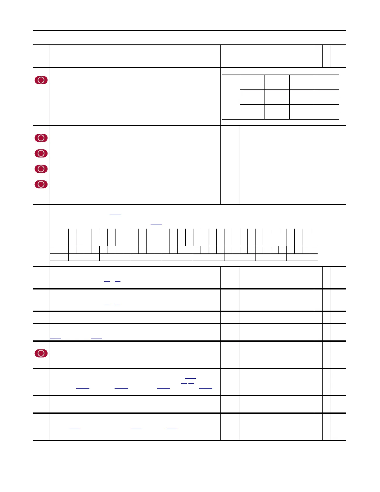
910 SL Tx Comm Format
Defines the node's communication format for transmitting SynchLink data. This determines the number of axis
data words, direct data words and buffered data words transmitted. Configure the format by using the Peer
Communication window in the DriveExecutive™ programming software.
• Value 14 can be used to allow the drive to transmit position data that can be used as a position reference.
Note: Option 14 was added and this parameter was changed to non-linkable for firmware version 3.001.
911
912
913
914
SL Tx DirectSel0
Determines the source type for the data transmitted by direct transmit word 0. The source type
selections are: no data, event, feedback and drive parameter.
SL Tx DirectSel1
Determines the source type for the data transmitted by direct transmit word 1. The source type
selections are: no data, event, feedback and drive parameter.
SL Tx DirectSel2
Determines the source type for the data transmitted by direct transmit word 2. The source type
selections are: no data, event, feedback and drive parameter.
SL Tx DirectSel3
Determines the source type for the data transmitted by direct transmit word 3. The source type
selections are: no data, event, feedback and drive parameter.
Note: These parameters were changed to non-linkable for firmware version 3.001.
Default:
Options:
0 =
0 =
1 =
2 =
3 =
4 =
5 =
6 =
7 =
8 =
9 =
10 =
11 =
12 =
13 =
“No Data”
“No Data” 14 = “Reserved”
“SL Multiply” 15 = “Reserved”
“Event P0” 16 = “Reserved”
“Event P1” 17 = “Reserved”
“Reserved” 18 = “Reserved”
“Reserved” 19 = “Reserved”
“Reserved” 20 = “Reserved”
“Reserved” 21 = “Dir Tx Data”
“Reserved” 22 = “Dir Rx Data”
“Reserved” 23 = “E0 Accum”
“Event Status” 24 = “E1 Accum”
“Reserved” 25 = “Opt0 Accum”
“Reserved” 26 = “Opt1 Accum”
“Reserved”
915
916
SL Rcv Events
Displays the received event status from Par 917 [SL Rx P0 Regis].
SL Clr Events
Set these bits to clear the corresponding event latches indicated in Par 915 [SL Rcv Events].
917 SL Rx P0 Regis
Displays received port 0 registration data, if direct received data is configured to be port 0 registration data by the
Rx Direct Data Selector (Parameters 905…909). Configure this selection by using the Peer Communication
window.
Default:
Min/Max:
0
-/+2147483648
RO 32-bit
Integer
918 SL Rx P1 Regis
Displays received port 1 registration data, if direct received data is configured to be port 1 registration data by the
Rx Direct Data Selector (Parameters 905…909). Configure this selection by using the Peer Communication
window.
Default:
Min/Max:
0
-/+2147483648
RO 32-bit
Integer
921 SL Real2DInt In
Provides the floating point (real) input to the real to integer conversion function.
Default:
Min/Max:
0.0000
-/+16.0000
Y
RW Real
922 SL Real2DInt Out
Displays the integer output of the real to integer conversion function. The value is the result of the formula:
Par
921 [SL Real2DInt In] x Par 923 [SL Mult Base].
Default:
Min/Max:
0
0/65535
RO 16-bit
Integer
923 SL Mult Base
Specifies the base for SynchLink real to integer and integer to real conversion functions. Determines the
resolution of the conversion results. You must use the same value at the transmitting node and receiving /
multiplying nodes. Enter a value that will not produce an overflow - the product of this value and the inputs to
the conversion and multiply functions must be less than 65,536.
Default:
Min/Max:
10000.0000
0.2000/50000.0000
RW Real
924 SL Mult A In
Displays the A Multiplier Input, as a floating point (real) value. This value is divided by the Par 923 [SL Mult Base].
The source of the A Multiplier is determined by the Rx Direct Data Selector (Parameters 905
-909). The possible
sources are: zero, Par
1054 [MulDiv 1 Mul], Par 1056 [MulDiv 1 Result], Par 1058 [MulDiv 2 Mul], or Par 1060
[MulDiv 2 Result]. The SynchLink Multiply function takes this input before it is converted to floating point.
Default:
Min/Max:
0.0000
0.0000/65535.0000
RO Real
925 SL Mult B In
The B Multiplier Input. This must be a floating point (real) value. The SynchLink Multiply function takes this input
after it is converted to integer.
Default:
Min/Max:
1.0000
0.25000/2.0000
Y
RW Real
926 SL Mult Out
Displays the output of the SynchLink Multiply function as a floating point (real) value. The value is the result of
the formula: Par
924 [SL Mult A In] source (integer) x Par 925 [SL Mult B In] / Par 923 [SL Mult Base] or Par
924 [SL Mult A In] x Par 925 [SL Mult B In].
Note: The SynchLink Multiply function produces an output that is always positive.
Default:
Min/Max:
0.0000
0.0000/65535.0000
RO Real
No. Name
Description
Values
Linkable
Read-Write
Data Type
Value Axis (A) Direct (D) Buffered (B)
Options 0000
70218
9048
141314
170418
Options
Reserved
Reserved
Reserved
Reserved
Reserved
Reserved
Reserved
Reserved
Reserved
Reserved
Reserved
Reserved
Reserved
Reserved
Reserved
Reserved
Reserved
Reserved
Reserved
Reserved
Reserved
Reserved
Reserved
Reserved
Reserved
Opt0 Regis
Reserved
Reserved
Reserved
Reserved
E1 Regis
E0 Regis
Default xxxxxxxxxxxxxxxxxxxxxxxxx0xxxx00
Bit 313029282726252423222120191817161514131211109876543210
0 = False
1 = True
 Loading...


