Rockwell Automation Publication 20D-PM001D-EN-P - March 2019 147
Troubleshooting Chapter 3
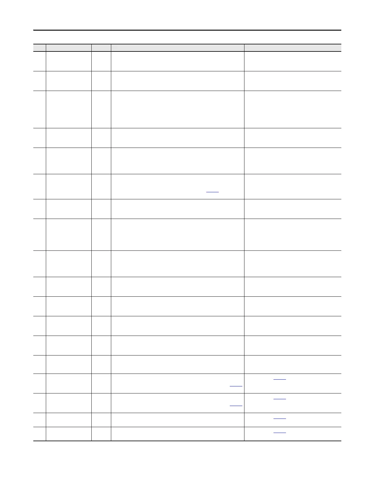
66 HiHp Bus Com Dly 1 (High Horse Power Only)
Bus Communication Time Delay - the communication bus has delayed
feedback or bad communication quality.
Check the communication bus lines - 10 pin connector
on the Main Control board, Fiber Optic Power Interface
board, and fiber optic connections.
67 HiHp Bus Link Ls 1 (High Horse Power Only)
Bus Communication Link Loss - bus communication between the Fiber Optic
Power Interface board and the Voltage Feedback board has stopped.
Check the communication bus lines - 10 pin connector
on the Main Control board, Fiber Optic Power Interface
board, and fiber optic connections.
68 HiHp Bus CRC Er 1 (High Horse Power Only)
Bus Communication CRC Error - too many Cycling Ring Checksum (CRC) errors
have occurred in the communication bus.
A fast power cycle may cause the 700S Main Control board to attempt to
communicate with the ASIC board before the ASIC board is energized.
Check the communication bus lines - 10 pin connector
on the Main Control Board, Fiber Optic Power Interface
board, and fiber optic connections.
69 HiHp Bus WtchDog 1 (High Horse Power Only)
Bus Communication Watchdog Error, No message (packets) came through in
the communication bus - a watchdog error was detected.
Check the communication bus lines - 10 pin connector
on the Main Control board, Fiber Optic Power Interface
board, and fiber optic connections.
70 HiHp Fan Fdbk Ls 1 (High Horse Power Only)
Fan Feedback Loss - an inverter cooling fan did not send active feedback or did
not work.
• Check the communication bus lines - 10 pin
connector on the Main Control board, Fiber Optic
Power Interface board, and fiber optic connections.
• Check the inverter cooling fans.
71 HiHp Drv OvrLoad 1 (High Horse Power Only)
Drive Overload - the drive's operating point has exceeded the intermittent
current rating and a foldback to the continuous rating in Par
400 [Rated Amps]
has occurred.
Reduce the mechanical load.
72 HiHp PwrBd PrcEr 1 (High Horse Power Only)
Power Board Processor Error - a processor on the Fiber Optic Power Interface
circuit board has detected a self diagnostic problem.
Replace the Fiber Optic Power Interface board.
73 HiHp PrChrg Cntc 1 (High Horse Power Only)
Precharge Contactor Fault - the precharge contactor did not send back active
feedback.
• If the drive has AC input, check the precharge resistor
and contactor.
• If the drive has DC input, check the jumper for
precharge bypass switch on the Fiber Optic Power
Interface board.
74 HiHp PwrEE Error 1 (High Horse Power Only)
Power EEPROM Error - the Cycling Ring Checksum (CRC) of the data stored in
the Fiber Optic Power Interface board’s EEPROM does not match the stored
CRC.
• Cycle power to the drive.
• Check the communication bus lines - 10 pin
connector on the Main Control board, Fiber Optic
Power Interface board, and fiber optic connections.
75 HiHP PwrBd Otemp 1 (High Horse Power Only)
Power Board Over Temperature - the temperature of the Fiber Optic Power
Interface board has exceeded 85° C.
Lower the ambient temperature.
76 HiHP HardwareVer 3 (High Horse Power Star-coupler Frame 12 & 14 Drives Only)
The left and right side inverter units have different current ratings or the ASIC
board or the Fiber Optic Power Interface board is not functioning.
Check the version of each inverter (left and right units),
then replace the unit.
77 HiHP CurrUnblnce 3 (High Horse Power Star-coupler Frame 12 & 14 Drives Only)
The output current between the left and right side inverter units are
unbalanced (20% of current feedback rating, e.g. 184A = 920A * 0.2).
Check the motor wiring for each unit.
78 HiHP VoltUnblnce 3 (High Horse Power Star-coupler Frame 12 & 14 Drives Only)
The bus voltage for the left and right side inverter units is unbalanced (6% of
normal bus voltage, e.g. 41Vdc = 675Vdc * 0.06).
Check the input power and wiring for each unit.
79 HiHP Bus Data 3 (High Horse Power Star-coupler Frame 12 & 14 Drives Only)
Communication Bus data are mismatched between the left and right side unit.
Check communication bus lines - 10 pin connector on
Main Control board, Fiber Optic Power Interface board
and fiber optic connections.
81 + Soft Over Trvl 2 (Motion Only)
The position feedback exceeds the maximum positive travel setting in Par
694
[Motn Mx Pos Trvl].
Configured with Par
395 [+Sft OvrTrvlCnfg].
82 - Soft Over Trvl 2 (Motion Only)
The position feedback exceeds the maximum negative travel setting in Par 695
[Motn Mx Neg Trvl].
Configured with Par
396 [-Sft OvrTrvlCnfg].
83 + Hard Over Trvl 2 (Motion Only)
The signal for the hardware positive over travel appears on a digital input.
Configured with Par
397 [+Hrd OvrTrvlCnfg].
84 - Hard Over Trvl 2 (Motion Only)
The signal for the hardware negative over travel appears on a digital input.
Configured with Par
398 [-Hrd OvrTrvlCnfg].
No. Name Type
(1)
Description Action
 Loading...


