148 Rockwell Automation Publication 20D-PM001D-EN-P - March 2019
Chapter 3 Troubleshooting
For Allen-Bradley Drives Technical Support:
For Automation and Control Technical Support:
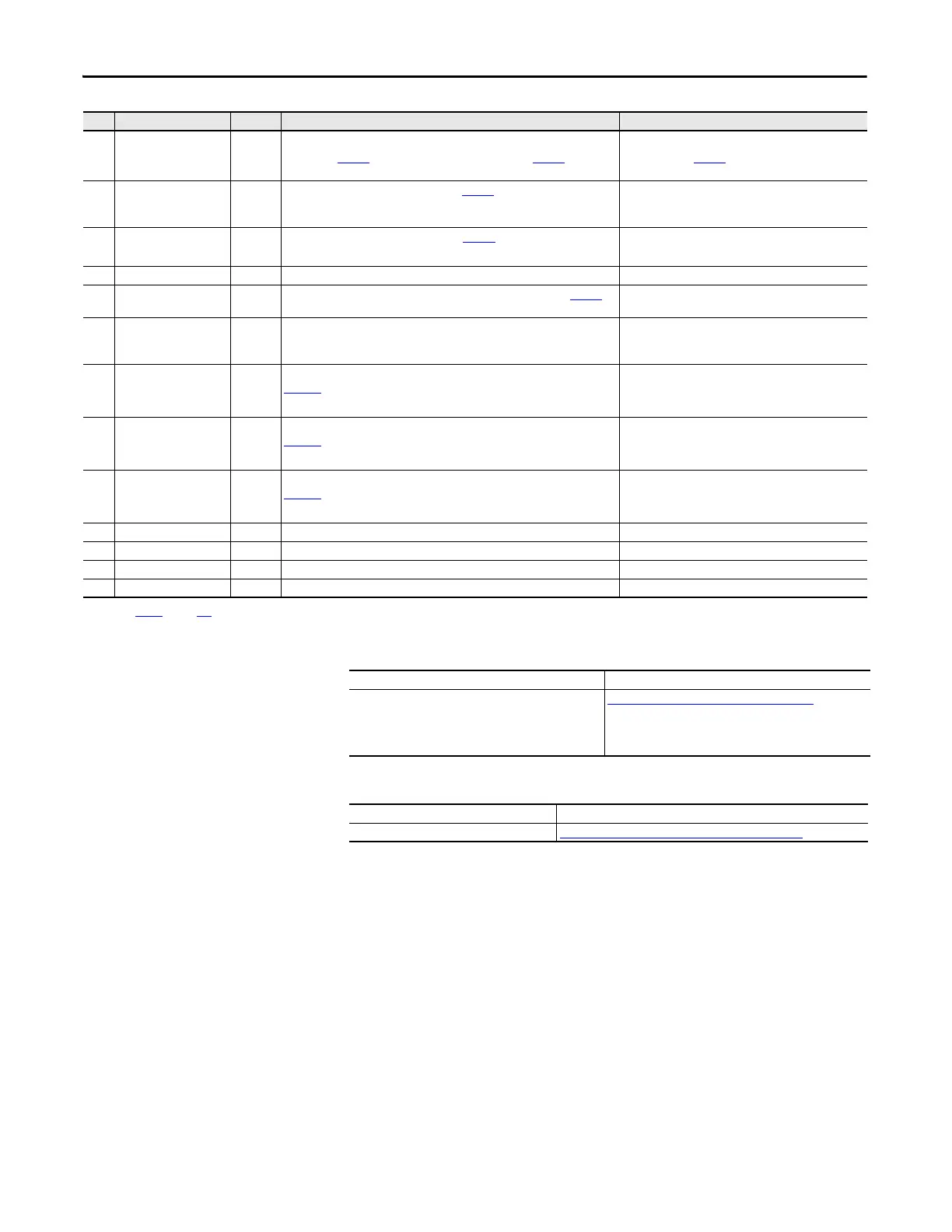
85 Position Error 2 (Motion Only)
The value of Par 769 [Position Error] exceeded the value of Par 696 [Motn
PositErrTol].
Verify the value in Par 696 [Motn PositErrTol].
Configured with Par 399 [Position ErrCnfg].
86 Drive Homing 3 When the drive is in Drive Homing mode (Par
740 [Position Control], bit 24 or
bit 27 is On), the Drive Homing Alarm triggers and the drive moves to a home
position automatically.
Check Par 740 [Position Control], bit14 “Find Home” or
bit 27 “Return Home”.
88 Stahl Optics 3 The Linear Stahl encoder detected a fault. Par
291 [Lin1Stahl Status] displays
the details of the fault.
• Reconnect encoder or replace encoder.
• Reconnect option feedback card.
89 Drv Waking 3 The Wake timer is counting toward a value that will start the drive.
92 Ride Thru 3 The Bus voltage has dropped to the Ride-Through level specified in Par
408
[Power Loss Level].
Check the AC input voltage and the DC bus voltage.
93 +/- 12volt Power Alarm 3 The12V DC control voltage is outside the tolerance range (Alarm). The positive
voltage power exceeds +15.50 V DC. The negative voltage power exceeds -
15.50V DC.
94 Analog In 1 Loss 1 Analog Input channel 1 is lost. For configuration of Analog Input channel 1, see
Par
1093 [Anlg In1LossCnfg].
• Check condition of Analog Input channel 1.
• Change configuration for parameter 1093 [Anlg
In1LossCnfg].
95 Analog In 2 Loss 1 Analog Input channel 2 is lost. For configuration of Analog Input channel 2, see
Par 1094 [Anlg In2LossCnfg].
• Check condition of Analog Input channel 2.
• Change configuration for parameter 1094 [Anlg
In2LossCnfg].
96 Analog In 3 Loss 1 Analog Input channel 3 is lost. For configuration of Analog Input channel 3, see
Par
1095 [Anlg In3LossCnfg].
• Check condition of Analog Input channel 3.
• Change configuration for parameter 1095 [Anlg
In3LossCnfg].
129 Faults Cleared * Indicates that all faults have been cleared. *Informational only.
130 Fault Q Cleared * Indicates that the fault queue has been cleared. *Informational only.
131 Alarm Cleared * Indicates that all alarms have been cleared. *Informational only.
132 Alarm Q Cleared * indicates that the alarm queue has been cleared. *Informational only.
(1) Refer to Tabl e 5 on page 142 for Fault Type Descriptions.
No. Name Type
(1)
Description Action
Title Online at…
Allen-Bradley Drives Technical Support http://www.rockwellautomation.com/literature
or
Call M-F, 7:00a.m. to 6:00p.m. Central STD time:
1.262.512.8176
Title Online at…
Rockwell Automation Technical Support http://support.rockwellautomation.com/knowledgebase
 Loading...


