56 Rockwell Automation Publication 20D-PM001D-EN-P - March 2019
Chapter 2 Programming and Parameters
263 Heidenhain0 Cnfg
Configures the Heidenhain Encoder Feedback Option.
• Bit 5 “Direction” determines the counting direction. Set to “0” to count up or forward. Set to “1” to count in reverse or down.
• Bit 6 “SW Reset” setting this bit to “1” resets and restarts the option card.
• Bit 7 “VM Direction” determines the direction of the encoder pulse output from the Heidenhain option card when bit 6 “VrtlMasterEn” of Par
266 [Heidn Encdr Type] is set. When this bit is off, =
“0”, the direction of the encoder pulse output is the same as Par
1155 [Heidn VM Pos Ref], and the reverse of Par 1155 when this bit is set, = “1”.
• Bits 10 -12 form a 3 bit moving average filter sampling rate. (See Table 263A: Sample Rate Bit Settings
).
Notes: This parameter was added for firmware version 2.003. This parameter was changed to non-linkable for firmware version 3.001. Added bit 7 for firmware version 4.001.
264 Heidenhain0 Stat
Indicates fault and alarm statuses on the Heidendhain encoder feedback option card and Endat communication.
• Bit 0 “VM Enc Out” when set, indicates that the encoder output from the Heidenhain option card is the virtual encoder position determined by Par
1155 [Heidn VM Pos Ref].
• Bit 1 “Emul Enc Out” when set, indicates that the encoder output from the Heidenhain option card is the emulated encoder position determined by the connected Heidenhain encoder.
• Bit 5 “Sig Amplitud” indicates that the signal amplitude is insufficient or too large.
• Bit 6 “Quadrate Er” indicates that there is a signal quadrature error.
• Bit 7 “Open Wire” indicates an open wire fault.
• Bit 8 “VoltageLvlEr” indicates that the operating voltage is too high or too low.
• Bit 9 “PowerSup Er” indicates the failure of the power supply.
• Bit 10 “PowerUpDiag Er” indicates the option board failed its power-up diagnostic test.
The pattern on the FPGA must be identical to the pattern written from the DSP, or the board status test will fail.
• Bit 11 “MsgChecksum Er” indicates a message checksum fault.
The check sum associated with the Endat communication device must be correct and acknowledged by the feedback option card.
• Bit 12 “Time Out Err” indicates an Endat time-out fault.
• Bit 13 “PPR Error” indicates an encoder PPR setting mismatch fault.
• Bit 14 “Bootup Error” indicates an Endat boot-up fault.
• Bit 15 “FW VersionEr” indicates that the firmware version of the encoder does not match the firmware version of the Heidenhain option card in the drive.
• Bit 16 “LightSrc Er” indicates an Endat light source fault.
• Bit 17 “Sig Amplitud” indicates an Endat signal amplitude fault.
• Bit 18 “PstvValue Er” indicates an Endat positive value fault.
• Bit 19 “Over Voltage” indicates an Endat over voltage fault.
• Bit 20 “Undr Voltage” indicates an Endat under voltage fault.
• Bit 21 “Over Current” indicates an Endat over current fault.
• Bit 24 “FrqExced Alm” indicates an Endat frequency exceeded alarm.
• Bit 25 “Temprtr Alm” indicates an Endat temperature exceeded alarm.
• Bit 26 “LghtCtrl Alm” indicates an Endat limit of light control alarm.
• Bit 28 “RefPoint Alm” indicates an Endat reference point alarm.
Notes: This parameter was added for firmware version 2.003. Bit 14 was changed from “Endat BootEr” to “Bootup Error” and bit 15 “FW VersionErr” is new for firmware version 3.001. Bits 0 and 1
were added for firmware version 4.001.
265 Heidn Mkr Offset
Configures marker offset values for the Heidenhain Encoder Feedback Option. The marker offset is specified
within one revolution.
Note: This parameter was added for firmware version 2.003.
Default:
Min/Max:
0.0000
0.0000/4294967295
Y
RW 32-bit
Integer
No. Name
Description
Values
Linkable
Read-Write
Data Type
Options
Reserved
Reserved
Reserved
Reserved
Reserved
Reserved
Reserved
Reserved
Reserved
Reserved
Reserved
Reserved
Reserved
Reserved
Reserved
Reserved
Reserved
Reserved
Reserved
SmplRate bt2
SmplRate bt1
SmplRate bt0
Reserved
Reserved
VM Direction
SW Reset
Direction
Reserved
Reserved
Reserved
Reserved
Reserved
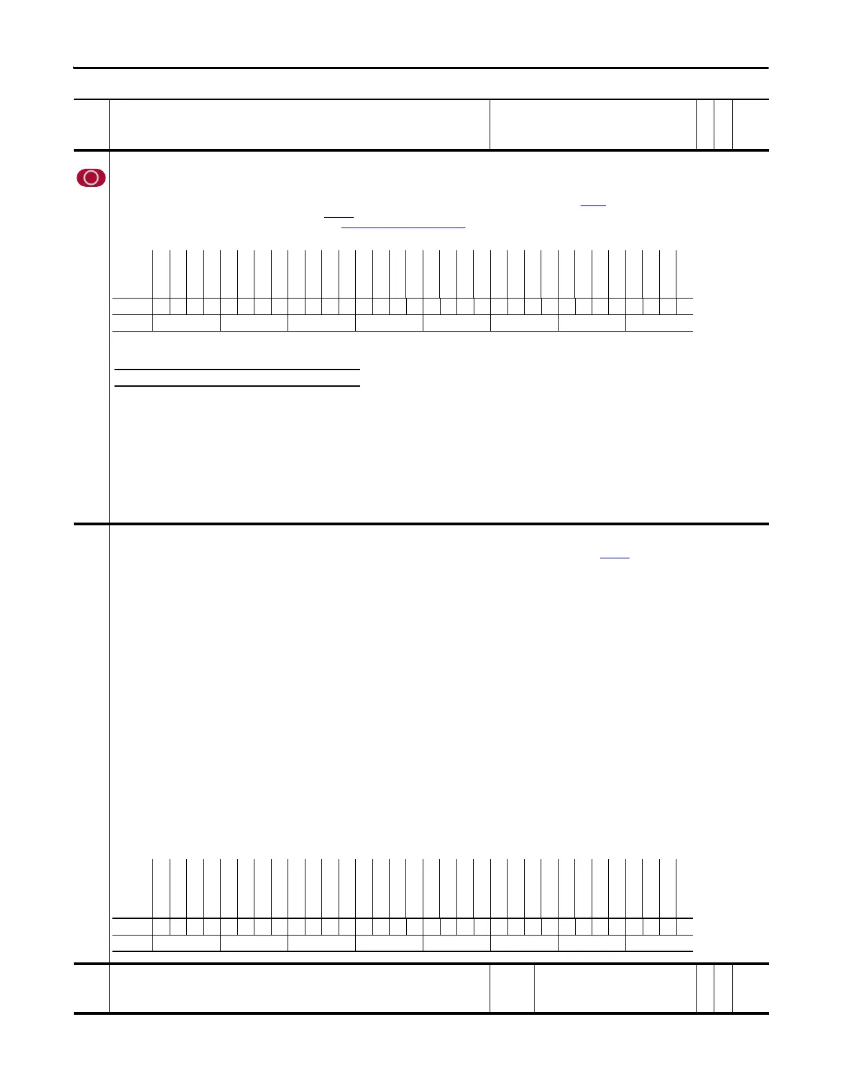
Default xxxxxxxxxxxxxxxxxxx011xx000xxxxx
Bit 313029282726252423222120191817161514131211109876543210
0 = False
1 = True
Table 263A: Sample Rate Bit Settings
Bit 12 11 10 Exponent Value ‘n’ Filter Sample Size = 2
n
0000 1
0011 2
0102 4
0113 8 (Default)
1004 16
1015 32
1106 64
1 1 1 7 127
Options
Reserved
Reserved
Reserved
RefPoint Alm
Reserved
LghtCtrl Alm
Temprtr Alm
FrqExced Alm
Reserved
Reserved
Over Current
Undr Voltage
Over Voltage
PstvValue Er
Sig Amplitud
LightSrc Er
FW VersionEr
Bootup Error
PPR Error
Time Out Err
MsgChecksum Er
PowerUpDiag Er
PowerSup Er
VoltageLvlEr
Open Wire
Quadrate Er
Sig Amplitud
Reserved
Reserved
Reserved
Emul Enc Out
VM Enc Out
Default xxx0x000xx00000000000000000xxx00
Bit 313029282726252423222120191817161514131211109876543210
0 = False
1 = True
 Loading...


