28 Rockwell Automation Publication 2198-RM006A-EN-P - December 2020
Chapter 2 Servo Drive and System Comparisons
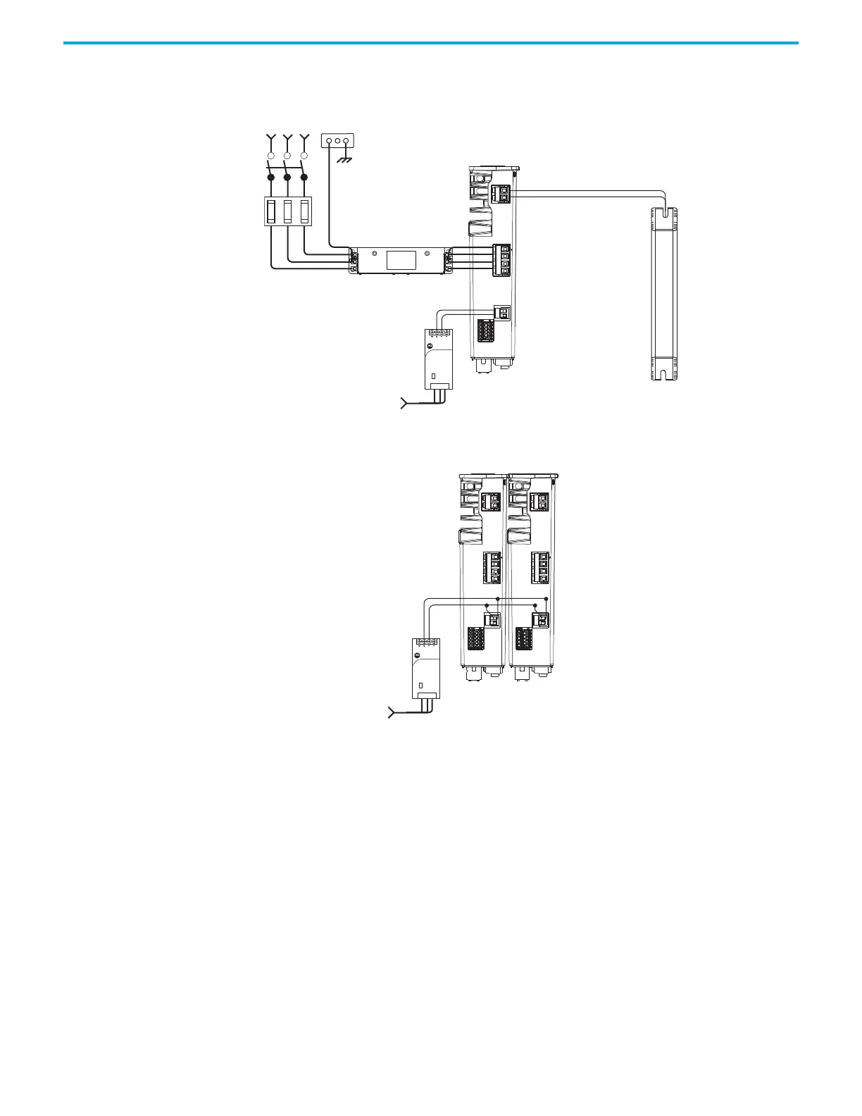
Figure 7 - Kinetix 5300 Servo Drive Input Power Example
Figure 8 - Typical Kinetix 5300 Installation without 24V Shared-bus Connectors
1606-XL
Power Supply
Input
Allen-Bradley
L3L2
L1
24+
DC+ SH
24-
SB+
SB-
S1
SC
S2
Single-phase or
Three-phase
Input Power
Line
Disconnect
Device
Circuit
Protection
2097-Rx or 2198-Rxxxx
Shunt Resistor
(optional component)
2198-Cxxxx-ERS Drive
(top view)
AC Input Power
Bonded Cabinet
Ground Bus
Mains AC Input Wired to
Standard Input Connector
1606-XLxxx
24V DC Control, Digital Inputs,
and Motor Brake Power
(customer-supplied)
24V DC Input Wired to
Standard Input Connector
2198-DBxx-F or
2198-DBRxx-F
AC Line Filter
(required for CE)
1606-XL
Power Supply
Input
Allen-Bradley
L3L2
L1
DC+ SH
SB+
SB-
S1
SC
S2
L3L2
L1
DC+ SH
SB+
SB-
S1
SC
S2
24+
24-
24+
24-
2198-Cxxxx-ERS Drives
(top view)
AC Input Power
24V DC connector wiring (control power input)
to additional Kinetix 5300 servo drives.
1606-XLxxx
24V DC Control, Digital Inputs,
and Motor Brake Power
(customer-supplied)
 Loading...


