38 Rockwell Automation Publication 2198-RM006A-EN-P - December 2020
Chapter 2 Servo Drive and System Comparisons
Table 29 - Ultra3000 Drives Digital Outputs
Figure 11 - Transistor Output Hardware Configuration
Table 30 - Relay Output Specifications
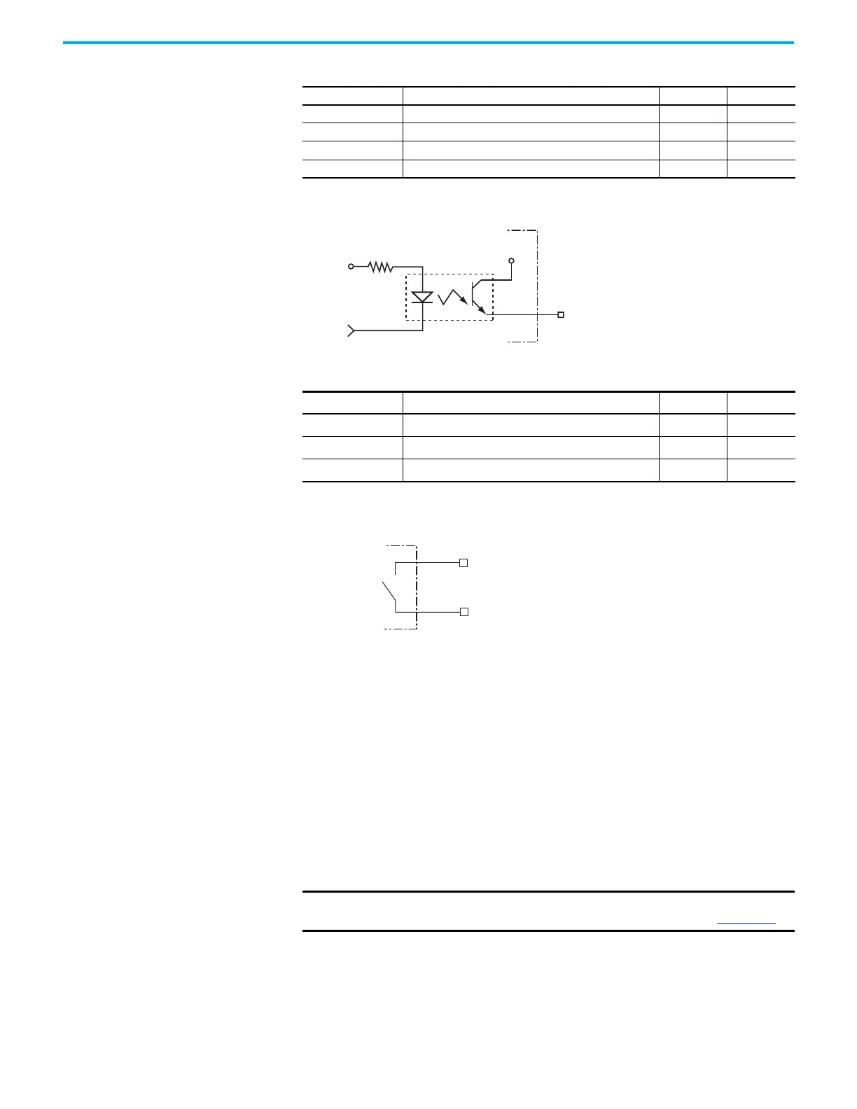
Figure 12 - Relay Output Configuration
Kinetix 5300 Servo Drive Digital Inputs
Four digital inputs are available for the machine interface on the I/O connector
and six configurable functions can be chosen from in the Studio 5000 Logix
Designer® application (version 33.00 or later). Digital inputs require a 24V DC
@ 15 mA supply. These are sinking inputs that require a sourcing device. A
common and cable shield connection is provided on the I/O connector for
digital inputs.
Although any input can be configured as a registration input, only two inputs
can be assigned at any time.
Parameter Description Min Max
ON state current Current flow when the output transistor is ON — 50 mA
OFF state current Current flow when the output transistor is OFF — 0.1 mA
ON state voltage Voltage across the output transistor when ON — 1.5V
OFF state voltage Voltage across the output transistor when OFF — 50V
Parameter Description Min Max
ON state current Current flow when the relay is closed — 1 A
ON state resistance Contact resistance when the relay is closed — 1 Ω
OFF state voltage Voltage across the contacts when the relay is open — 30V
IMPORTANT
To improve registration input EMC performance, see the System Design
for Control of Electrical Noise Reference Manual, publication GMC-RM001.
+5V
OUTPUT
IOPWR
OUT
Ultra3000 Drive
CN1-43
Relay +
CN1-44
Relay -
Normally
Open
Relay
Ultra3000 Drive
 Loading...


