Rockwell Automation Publication 2198-RM006A-EN-P - December 2020 45
Appendix A
Connectors and Field Connections
Connector Locations Use these illustrations to identify the connectors and indicators for the
Ultra™ 3000 and Kinetix® 5300 servo drives.
Ultra3000 Servo Drive Connector Data
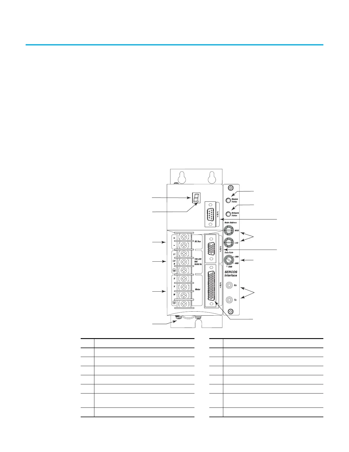
Figure 15 - Ultra3000 Servo Drive Front Panel Connections for Cat. No. 2098-DSD-005-SE, -010-SE,
and -020-SE
Item Description Item Description
1 Motor Power Cable Shield Clamp 8 Network Status Indicator
2 Motor Power Connections 9 CN3 9-pin Serial Port Connector
3 AC Input Power Connections 10 Node Address Switches
4 DC Bus Connections for Active Shunt Resistor Kit 11 CN2 15-pin Motor Feedback Connector
5 Logic Power Status Indicator 12 Data Rate Switch
6 Seven Segment Status Indicator 13
Sercos Interface Receive (Rx) and Transmit (Tx)
Connectors
7 Module Status Indicator 14 CN1 44-pin User I/O Connector

 Loading...


