Rockwell Automation Publication 2198-RM006A-EN-P - December 2020 69
Appendix D
Interconnect Diagrams
This appendix describes power wiring examples to help with the comparison
of the power wiring for the Ultra™ 3000 servo drive and the Kinetix® 5300 drive
systems.
Ultra3000 Servo Drive
Power Wiring Examples
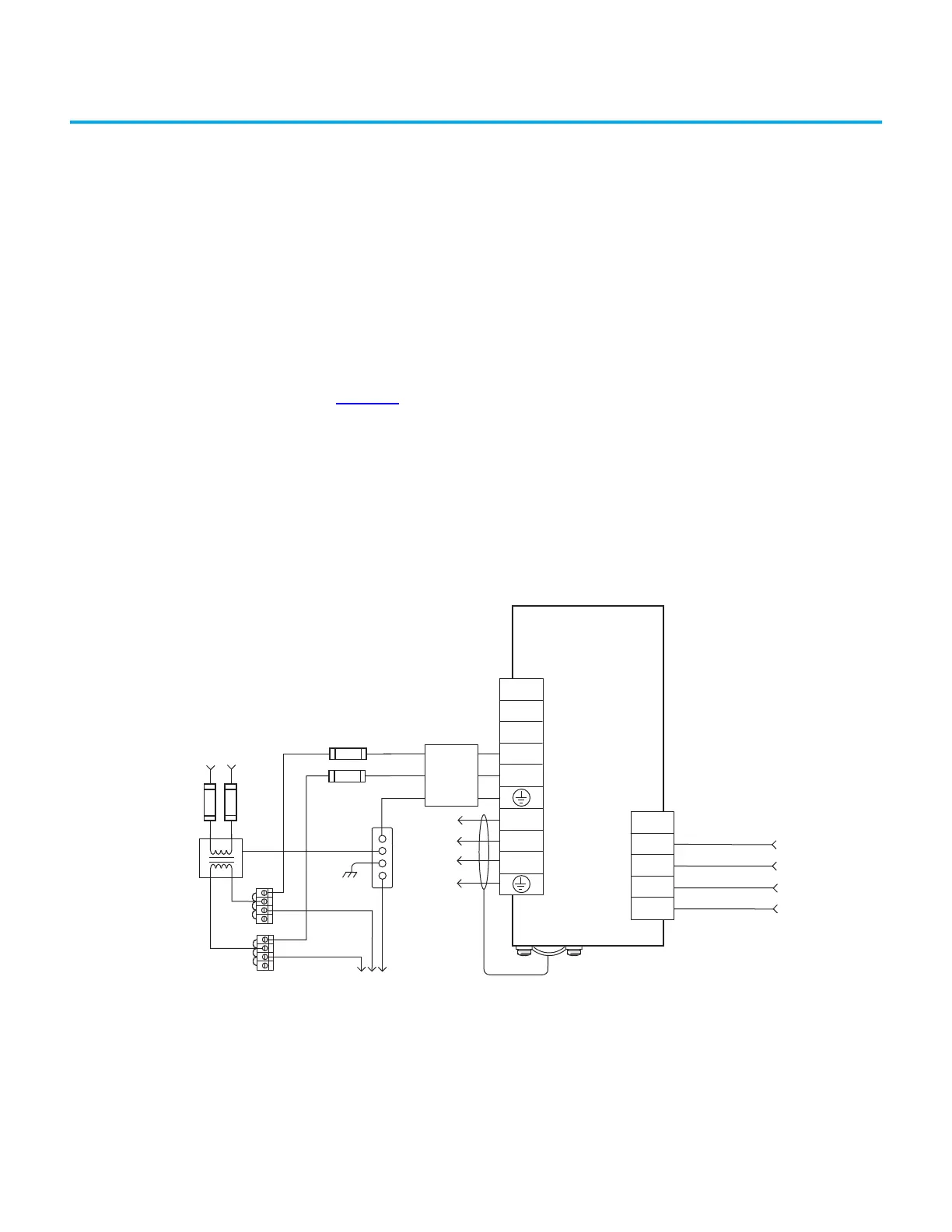
Figure 21 shows the power wiring diagram with 24V DC control string for
2098-DSD-005-SE, 2098-DSD-010-SE, and 2098-DSD-020-SE Ultra3000
Sercos drives. To avoid a separate 5V DC auxiliary logic power supply, the 24V
to 5V converter breakout board (catalog number 2090-U3CBB-DMxx) is used
to wire the control interface (CN1) connector.
For Sercos drives, input line contactor is part of the PLC program and output
control.
Figure 21 - Typical Power Wiring on Ultra3000 (230V) System
TB1
DC+
DC-
L1
L2/N
U
V
W
L2/N
L1
CN1
43
44
3
2
2098-DSD-005-SE,
2098-DSD-010-SE, and
2098-DSD-020-SE
Ultra3000 Digital Servo Drives
DC Bus Connections
for Active Shunt Module
AC Input Power
Connections
Motor Power
Connections
Single-phase
AC Line Filter
Input Fusing*
Single-phase AC Line
50/60 Hz
Fused Disconnect
or Circuit Breaker*
Isolation
Transformer*
Chassis
Bonded Cabinet
Ground Bus*
Terminal
Blocks*
To additional
Ultra3000 Drive
Three-phase
Motor Power
Connections
Cable Shield
Clamp
* INDICATES USER-SUPPLIED COMPONENT
N.O. Relay Output+
N.O. Relay Output-
Aux Logic Power In +5V
Aux +5V Common
From CN1 Breakout
Board with 24V to 5V
Aux Power Converter
(2090-U3CBB-DMxx)
Single-phase Input
100…240V AC rms

 Loading...


