70 Rockwell Automation Publication 2198-RM006A-EN-P - December 2020
Appendix D Interconnect Diagrams
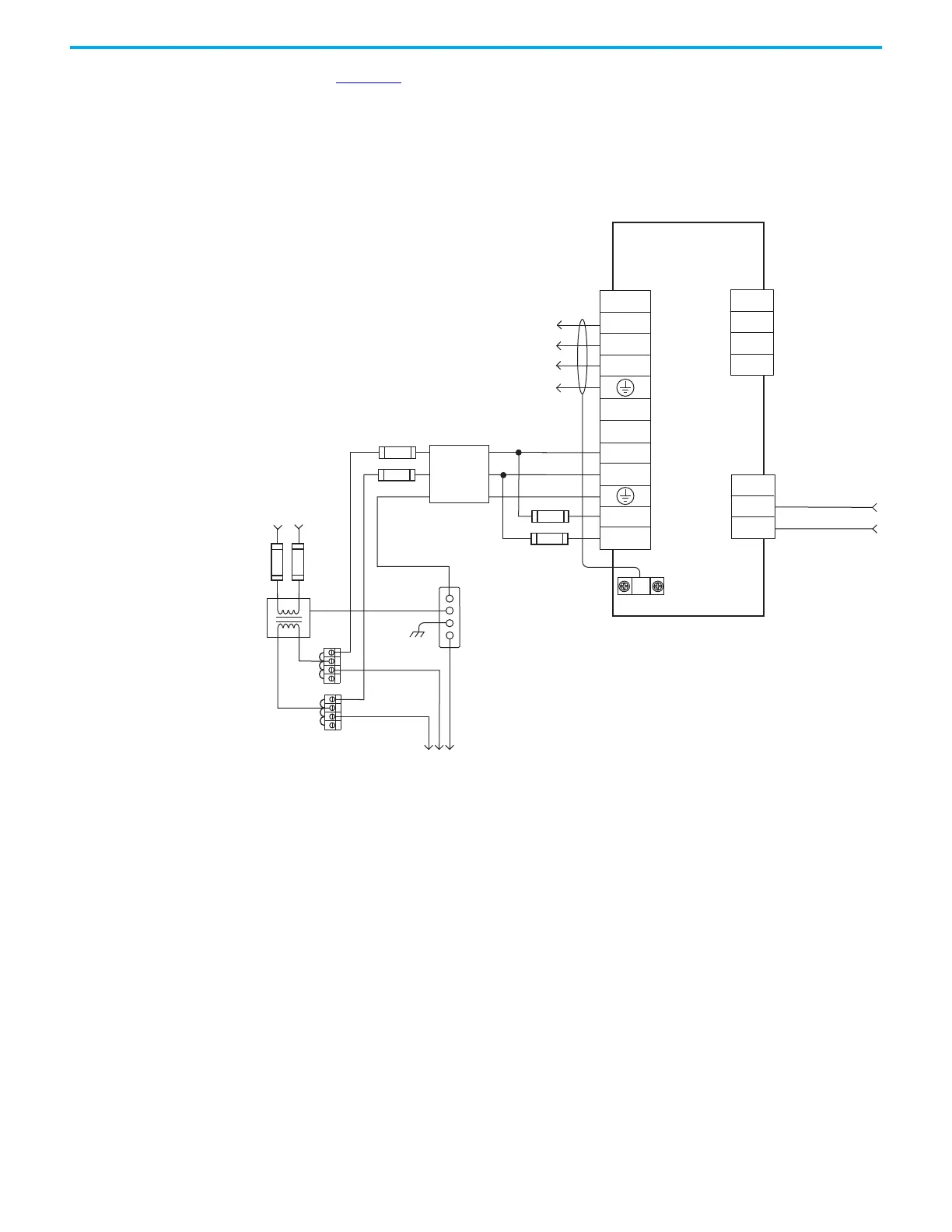
Figure 22 shows the power wiring diagram with 24V DC control string for the
2098-DSD-030-SE Sercos drive.
For Sercos drives, input line contactor is part of the PLC program and output
control.
Figure 22 - Typical Power Wiring on Ultra3000 (230V) System
TB1
U
V
W
DC+
DC-
L1
L2/N
L1 AUX
L2/N AUX
CN1
43
44
TB2
1
2
3
N.O. Relay Output+
N.O. Relay Output-
External Passive
Shunt Connections
2098-DSD-030-SE
Ultra3000 Digital Servo Drive
L2/N
L1
Input Fusing*
Input Fusing*
Single-phase AC Line
50/60 Hz
Fused Disconnect
or Circuit Breaker*
Isolation
Transformer*
Chassis
Bonded Cabinet
Ground Bus*
Terminal
Blocks*
To additional
Ultra3000 Drive
* INDICATES USER-SUPPLIED COMPONENT
Single-phase Input
100…240V AC rms
Single-phase
AC Line Filter
Three-phase
Motor Power
Connections
AC Input Power
Connections
Motor Power
Connections
Cable Shield
Clamp
 Loading...


