52 Rockwell Automation Publication 2198-RM006A-EN-P - December 2020
Appendix A Connectors and Field Connections
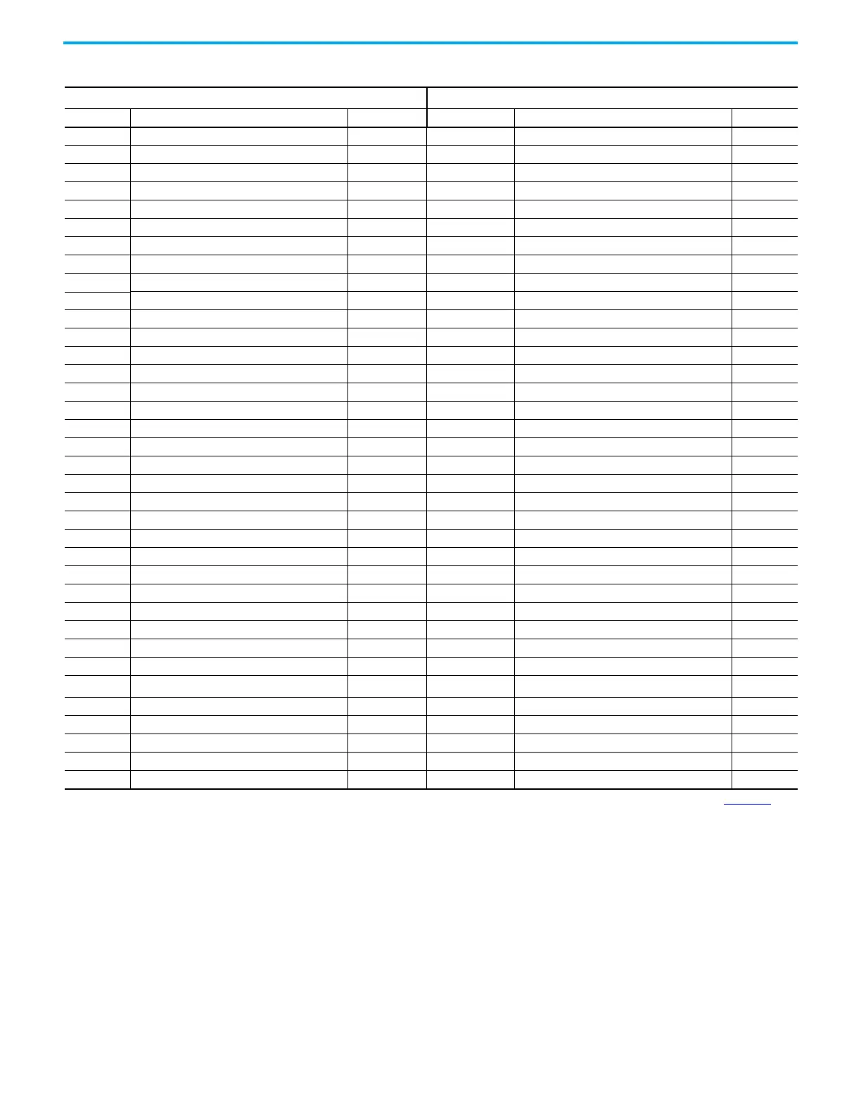
9 Auxiliary Encoder Ch I- IX- AUX_EPWR_5V Encoder 5V power output 9
10 Unbuffered Motor Encoder Ch A+ AM+
SHIELD Auxiliary feedback cable shield termination point. 10
11 Unbuffered Motor Encoder Ch A- AM- IN3 24V current-sinking fast input #3. 11
12 Unbuffered Motor Encoder Ch B+ BM+ COM I/O common for customer-supplied 24V supply. 12
13 Unbuffered Motor Encoder Ch B- BM- IN4 24V current-sinking fast input #4. 13
14 Unbuffered Motor Encoder Ch I+ IM+ COM I/O common for customer-supplied 24V supply. 14
15 Unbuffered Motor Encoder Ch I- IM- SHIELD I/O cable shield termination point. 15
16 Buffered Motor Encoder Ch A+ AMOUT+ AUX_AM– AM Differential Input – 16
17 Buffered Motor Encoder Ch A- AMOUT- AUX_BM– BM Differential Input – 17
18 Buffered Motor Encoder Ch B+ BMOUT+ AUX_IM– IM Differential Input – 18
19 Buffered Motor Encoder Ch B- BMOUT- AUX_COM Auxiliary common 19
20 Buffered Motor Encoder Ch I+ IMOUT+ SHIELD Auxiliary feedback cable shield termination point. 20
21 Buffered Motor Encoder Ch I- IMOUT- — — —
22 Common ACOM — — —
23 Programmable Analog Output AOUT — — —
24 Analog Current Limit Input ILIMIT — — —
25 Command + COMMAND+ — — —
26 Command - COMMAND- — — —
27 I/O Common IOCOM — — —
28 I/O Common IOCOM — — —
29 I/O Power IOPWR — — —
30 I/O Power IOPWR — — —
31 Digital Input 1 INPUT1 — — —
32 Digital Input 2 INPUT2 — — —
33 Digital Input 3 INPUT3 — — —
34 Digital Input 4 INPUT4 — — —
35 Digital Input 5 INPUT5 — — —
36 Digital Input 6 INPUT6 — — —
37 Digital Input 7 INPUT7 — — —
38 Digital Input 8 INPUT8 — — —
39
Digital Output 1
(2)
OUTPUT1 — — —
40 Digital Output 2 OUTPUT2 — — —
41 Digital Output 3 OUTPUT3 — — —
42 Digital Output 4 OUTPUT4 — — —
43 Normally Open Relay Output+ RELAY+ — — —
44 Normally Open Relay Output- RELAY- — — —
(1) The I/O names and signals vary depending on the model of Ultra3000 you have installed, refer to the Ultra3000 Digital Servo Drives Installation Instructions, publication 2098-IN003 for
information on your specific model.
(2) READY signal only available with firmware revision 1.29 (or above). Requires use of drive-mounted breakout board (2090-U3BB2-DM44).
Table 39 - I/O Connector Pinouts (Continued)
Ultra3000 Servo Drives
(1)
Kinetix 5300 Servo Drives
CN1 Pin Description Signal Signal Description I/O Pin
 Loading...


