PowerFlex Digital DC Drive User Manual - Publication 20P-UM001C-EN-P - July 2008
Programming and Parameters 3-53
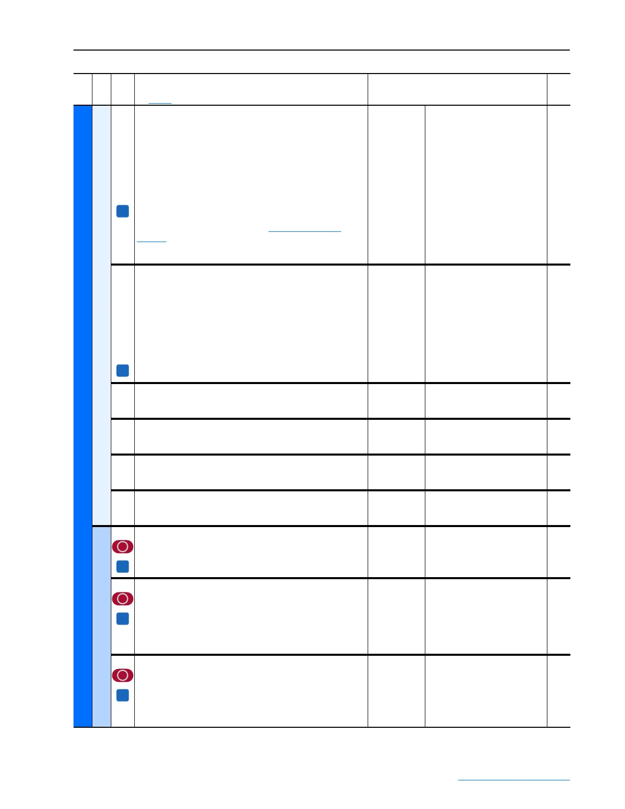
UTILITY
Faults
1351
1352
1353
1354
1355
1356
1357
1358
1359
1360
[Fault 1 Code]
[Fault 2 Code]
[Fault 3 Code]
[Fault 4 Code]
[Fault 5 Code]
[Fault 6 Code]
[Fault 7 Code]
[Fault 8 Code]
[Fault 9 Code]
[Fault 10 Code]
A code that represents the fault that tripped the drive. The codes will
appear in these parameters in the order they occur (i.e., [Fault 1
Code] = the most recent fault). Refer to Fault Descriptions on
page 4-4 for a list of possible codes.
Note: Par 1351 [Fault 1 Code] is accessible via the Basic Parameter
view.
Default:
Min/Max:
Read Only
0 / 32768
1361
1362
1363
1364
1365
1366
1367
1368
1369
1370
[Fault 1 Time]
[Fault 2 Time]
[Fault 3 Time]
[Fault 4 Time]
[Fault 5 Time]
[Fault 6 Time]
[Fault 7 Time]
[Fault 8 Time]
[Fault 9 Time]
[Fault 10 Time]
The time between initial drive power up and the occurrence of the
associated trip fault.
Default:
Min/Max:
Units:
Read Only
0.000 / 134000000.000
hr.
1371 [Fault Arm Amps]
Captures and displays the armature current (as a percentage of rated
current) at the time of the last fault.
Default:
Min/Max:
Units:
Read Only
–/+200
%
1372 [Fault Speed]
Captures and displays the output speed (rpm) of the drive at the time
of the last fault.
Default:
Min/Max:
Units:
Read Only
– / +32766
RPM
1373 [Fault Field Amps]
Captures and displays the field current (as a percentage of rated
current) at the time of the last fault.
Default:
Min/Max:
Units:
Read Only
0.00 / 100.00
%
1374 [Fault Voltage]
Captures and displays the armature voltage at the time of the last
fault.
Default:
Min/Max:
Units:
Read Only
- / + 999.00
Vdc
Alarms
203 [OverVolt Flt Cfg]
Determines the response of the drive to an overvoltage condition (F5
“Arm Overvoltage”).
Note: Refer to Chapter 4 for a list of alarm and fault descriptions.
Default:
Options:
2 =
0 =
1 =
2 =
“Fault”
“Ignore”
“Alarm”
“Fault”
354 [Aux Inp Flt Cfg]
Determines the response of the drive to an external fault condition
(F2 “Auxiliary Input”), i.e., no voltage at the digital input terminal
assigned to [Digital Inx Sel] with a value of 14 “Aux Fault”.
Notes: Refer to Chapter 4 for a list of alarm and fault descriptions.
Option 3 was changed from “Quick Stop “ to “Fast Stop” with firmware
version 2.001.
Default:
Options:
2 =
1 =
2 =
3 =
4 =
5 =
“Fault”
“Alarm”
“Fault”
“Fast Stop”
“Normal Stop”
“CurrLim Stop”
365 [OverTemp Flt Cfg]
Determines the response of the drive to a motor over temperature
condition (F16 “Motor Over Temp”).
Notes: Refer to Chapter 4 for a list of alarm and fault descriptions.
Option 3 was changed from “Quick Stop “ to “Fast Stop” with firmware
version 2.001.
Default:
Options:
2 =
0 =
1 =
2 =
3 =
4 =
5 =
“Fault”
“Ignore”
“Alarm”
“Fault”
“Fast Stop”
“Normal Stop”
“CurrLim Stop”
File
Group
No.
Parameter Name & Description
See page 3-2 for symbol descriptions
Values
Related
A
A
A
A
A
 Loading...


