PowerFlex Digital DC Drive User Manual - Publication 20P-UM001C-EN-P - July 2008
C-10 Application Notes
In addition you can configure the following:
• Enter the gain for the feed-forward signal in Par 787 [PID Source Gain]
• Monitor the feed-forward signal after the gain is applied in Par 758 [Feed
Fwd PID]
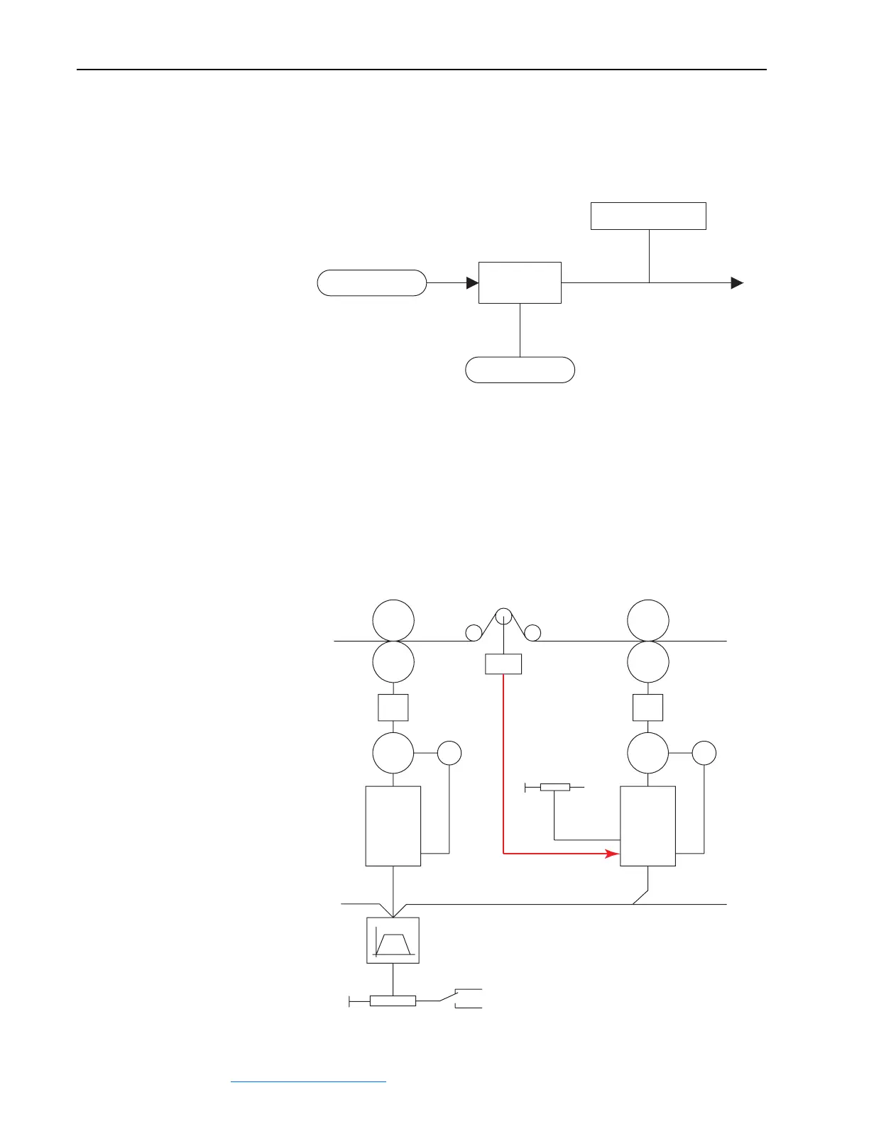
Configure the Feedback Signal in the Follower Drive(s)
The feedback signal originates from a load cell or a closed loop dancer and
is input to the drive via an analog input (typically analog input 1, due to the
ability to filter this signal).
• Set Par 70 [Anlg In1 Sel] to 19 “PID Feedback”.
Gain
P786
PID Source
P787
PID Source Gain
P758
Feed Fwd PID
Line Speed
Master
NIP-Roll
Reverse
Forward
Load Cell
0 - +10V
Tension Set
-10V
Set
Feedback
Line Speed Signal
Master
Drive
Slave
Drive
(Internal Ramp)
Line Speed Reference
+10V Forward
-10V Reverse
M
E
M
E
 Loading...


