PowerFlex Digital DC Drive User Manual - Publication 20P-UM001C-EN-P - July 2008
Installation and Wiring 1-37
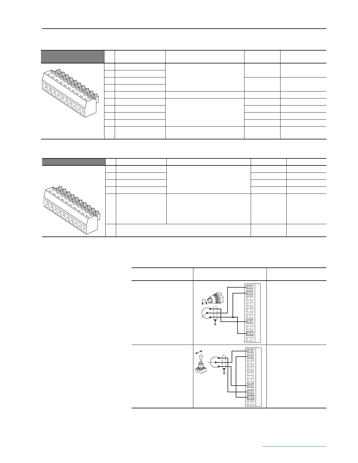
Table 1.S I/O Terminal Block 3 Designations
Table 1.T I/O Terminal Block 4 Designations
I/O Wiring Examples
No. Signal Description
Factory
Default Config. Parameter
21 Analog Output 1 (+) Max. ±10V, 5 mA. 12 “Motor Speed” 66 [Anlg Out1 Sel]
22 Analog Output 1 (–)
23 Analog Output 2 (+) 13 “Motor Curr” 67 [Anlg Out2 Sel]
24 Analog Output 2 (–)
25 Digital Output Common – –
26 Digital Output 1 Max. +30V, 50mA 5 “Ready” 145 [Digital Out1 Sel]
27 Digital Output 2 9 “Fault” 146 [Digital Out2 Sel]
28 Digital Output 3 2 “Spd Thresh” 147 [Digital Out3 Sel]
29 Digital Output 4 4 “CurrentLimit” 148 [Digital Out4 Sel]
30 External +24VDC Supply Supply voltage for the Digital Outputs.
Max. +30V DC, 80mA.
––
22
23
24
25
21
27
28
29
30
26
No. Signal Description Factory Default Config. Parameter
31 Digital Input 5 Max +30V, 15V/3.2mA, 24V/5mA,
and 30V/6.4mA.
17 “Speed Sel 1” 137 [Digital In5 Sel]
32 Digital Input 6 18 “Speed Sel 2” 138 [Digital In6 Sel]
33 Digital Input 7 19 “Speed Sel 3” 139 [Digital In7 Sel]
34 Digital Input 8 31 “Contactor” 140 [Digital In8 Sel]
35 Digital Input Common Important: When using the internal +24V
DC supply (terminal 19) for digital inputs
5-8, you must connect the digital input
common (terminal 35) to the +24V supply
common (terminal 18).
––
36-
40
Not Used – –
32
33
34
35
31
37
38
39
40
36
Input/Output Connection Example
Required Parameter
Changes
Potentiometer Unipolar
Speed Reference
10k Ohm Pot. Recommended
(2k Ohm Minimum)
• Adjust Scaling:
72 [Anlg In1 Scale] and
73 [Anlg1 Tune Scale]
• View Signal Value:
1404 [Analog In1 Value]
• View Signal Output:
385 [Speed Ref Out]
Joystick Bipolar Speed
Reference
(1)
±10V Input
• Set Direction Mode:
1322 [Direction Mode]
= 1 “Bipolar”
• Adjust Scaling:
72 [Anlg In1 Scale] and
73 [Anlg1 Tune Scale]
• View Signal Value:
1404 [Analog In1 Value]
• View Signal Output:
385 [Speed Ref Out]
1
2
3
4
5
6
7
8
9
10
1
2
3
4
5
6
7
8
9
10
 Loading...


