PowerFlex Digital DC Drive User Manual - Publication 20P-UM001C-EN-P - July 2008
Application Notes C-9
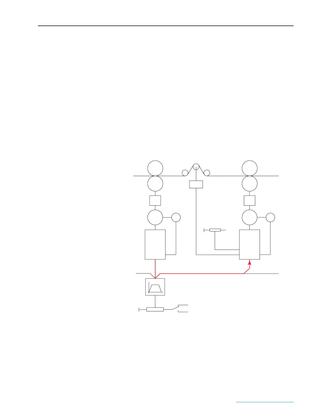
Configure a Line Speed Signal
The line speed signal is the main reference for the speed or current regulator
in the follower drive(s).
In the Master drive:
• Configure an analog output for the main speed reference (1 “Spd Ref
Out”)
In the Follower drive:
• Set Par 80 [Anlg In3 Sel] to 12 “UserDefined0”
• Set Par 786 [PID Source] to 8695 (503 + 8192). “503” = the parameter
number to which the signal from analog input 3 is sent (Par 503
[UserDefined0]), and “8192” is a drive internal fixed offset value.
Line Speed
Master
NIP-Roll
Reverse
Forward
Load Cell
0 - +10V
Tension Set
-10V
Set
Feedback
Line Speed Signal
Master
Drive
Slave
Drive
(Internal Ramp)
Line Speed Reference
+10V Forward
-10V Reverse
M
E
M
E
 Loading...


