PowerFlex Digital DC Drive User Manual - Publication 20P-UM001C-EN-P - July 2008
1-42 Installation and Wiring
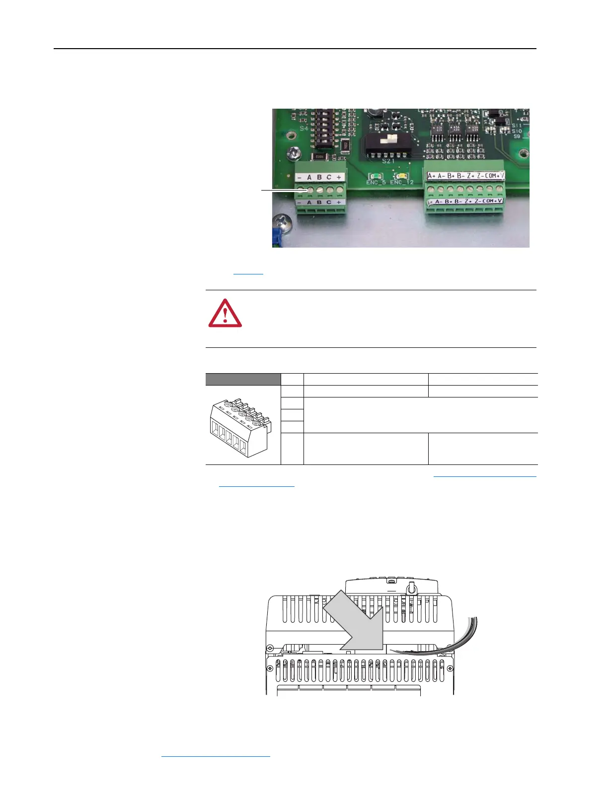
DC Analog Tachometer Terminal Block
Figure 1.35 Analog Tachometer Terminal Block Location
Refer to page A-3 for DC Analog Tachometer specifications.
Table 1.V DC Analog Tachometer Terminal Designations
I/O and Control Wire Routing
Route all I/O and control wires from through the bottom of the drive,
between the bottom front protective cover and the terminal cover (frame A)
or plastic covers (frames B and C).
!
ATTENTION: The Drive can overspeed if DIP switch S4 is set
incorrectly, or the tachometer is wired incorrectly. Failure to
observe this precaution could result in damage to, or destruction
of, the equipment.
No. Signal Description
– Negative input –
A (Not Used)
B
C
+ Positive input
Clockwise rotation = positive
Counterclockwise rotation = negative
22.7 / 45.4 / 90.7 / 181.6 /
302.9V
(1)
max voltage
8 mA max. current
(1)
Maximum voltage depends on the configuration of DIP switch S4. Refer to DC Analog Tachometer DIP Switch
S4 Example on page 1-34
Analog
Tachometer
terminal block
A
B
C
+
−
 Loading...


