PowerFlex Digital DC Drive User Manual - Publication 20P-UM001C-EN-P - July 2008
Installation and Wiring 1-41
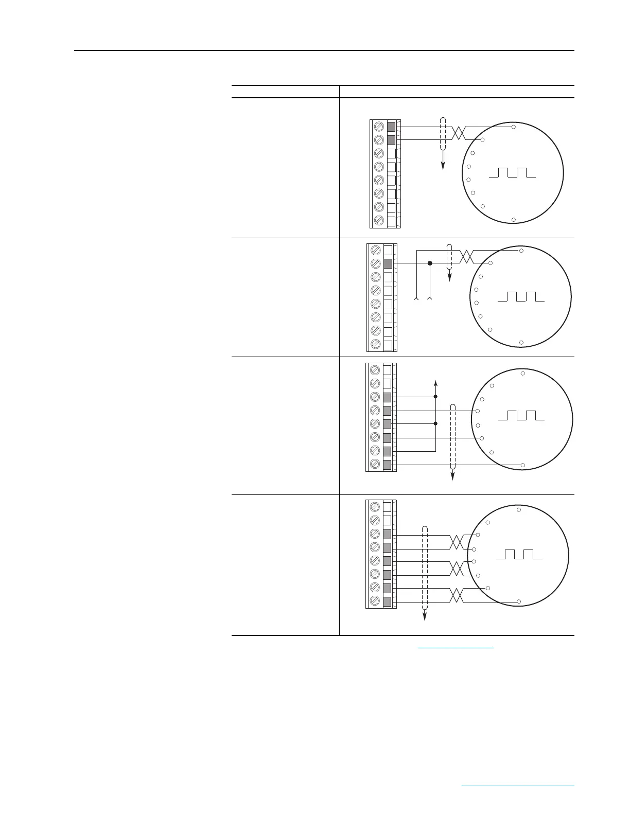
Figure 1.34 Sample Encoder Wiring
I/O Connection Example
Encoder Power –
(1)
Internal Drive Power
Internal (drive) +5/12-15V DC,
200mA
(1)
Shield connection is on drive Control EMI shield. Refer to Figure 1.33 on page 1-40.
Encoder Power –External
Power Source
Encoder Signal –
Single-Ended, Dual Channel
Encoder Signal –Differential,
Dual Channel
Common
+5/12-15V DC
(200 mA)
A+
A-
B+
B-
Z+
Z-
COM
+V
to Shield
(1)
+
Common
External
Power
Supply
to
Shield
(1)
A+
A-
B+
B-
Z+
Z-
COM
+V
B
B NOT
A NOT
A
Z
Z NOT
to Power
Supply Common
A+
A-
B+
B-
Z+
Z-
COM
+V
to Shield
(1)
B
B NOT
A NOT
A
Z
Z NOT
to Shield
(1)
A+
A-
B+
B-
Z+
Z-
COM
+V
 Loading...


