PowerFlex Digital DC Drive User Manual - Publication 20P-UM001C-EN-P - July 2008
Appendix G
Optional 115V AC to 24V DC I/O Converter
Circuit Board
What This Option Board
Provides
The 115V AC to 24V DC I/O Converter circuit board
(1)
allows you to
convert 115V AC digital input signals to 24V DC digital input signals in
order to interface with the standard digital I/O terminal blocks on the
PowerFlex DC drive Control board.
The card consists of:
• Eight (8) opto isolated 115V AC digital inputs
• Eight (8) interface outputs for the digital inputs on Control board of the
drive
(2)
• Two (2) input terminals for the 24V DC power supply voltage
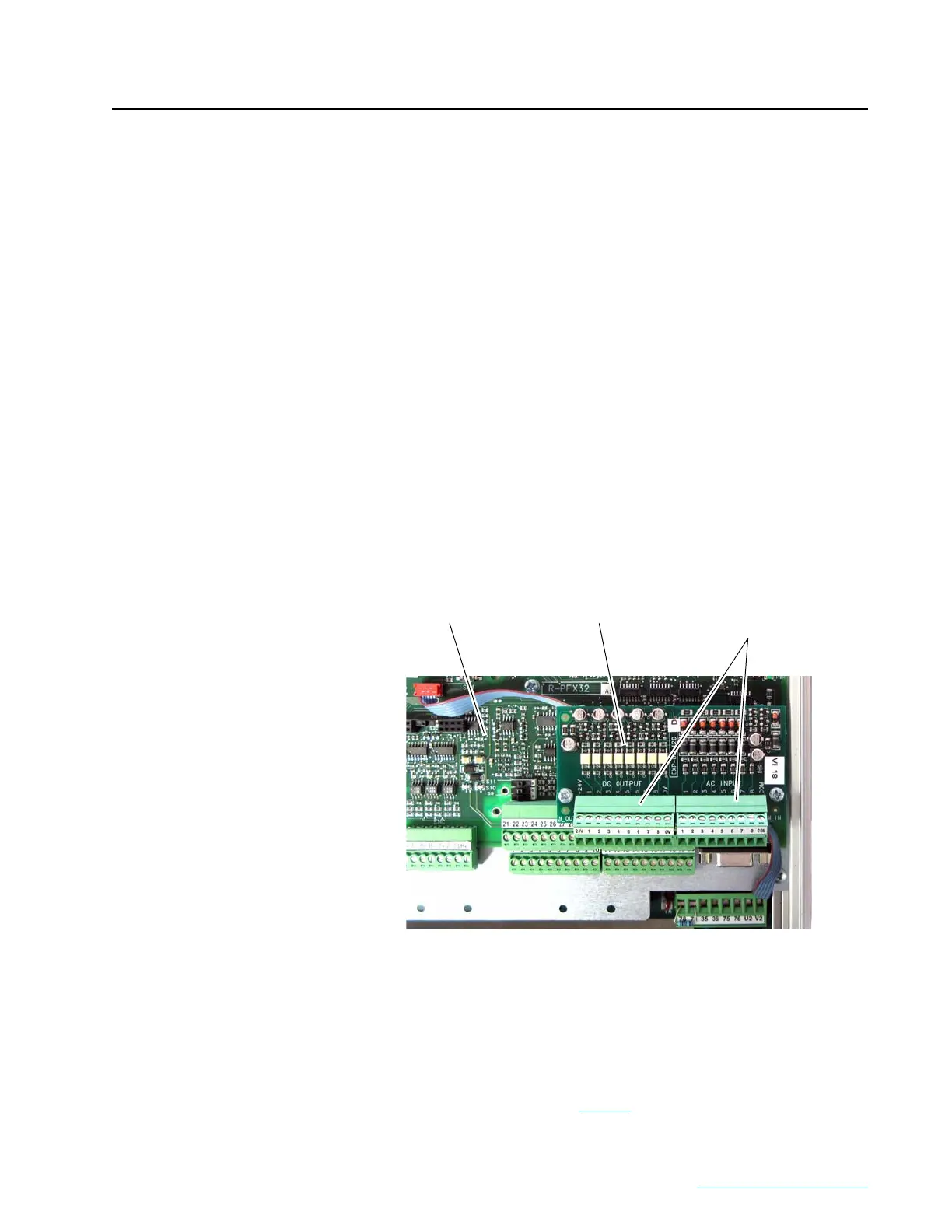
Figure G.1 115V AC to 24V DC I/O Converter Circuit Board Mounting Location
(1)
The 115V AC to 24V DC I/O Converter circuit board is not factory installed.
(2)
If more than eight 115V AC digital input signals require conversion to 24V DC (i.e., the optional PowerFlex DC
drive I/O Expansion circuit board is used - see Appendix F
), a second Converter board is required and must be
sourced and wired independently from the 115V AC to 24V DC I/O Converter board mounted on the Control
board and be mounted in an appropriate enclosure external to the PowerFlex DC drive enclosure.
Control Board I/O Converter Board I/O Converter Board
Terminal Blocks
 Loading...


