PowerFlex Digital DC Drive User Manual - Publication 20P-UM001C-EN-P - July 2008
F-2 Optional Analog and Digital I/O Expansion Circuit Board
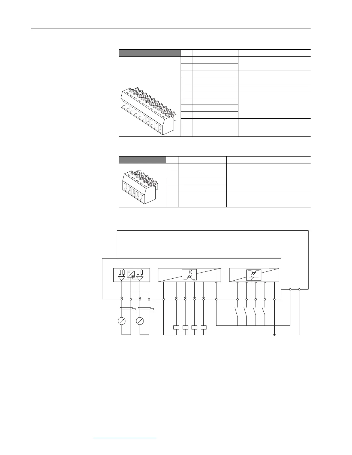
Table F.B I/O Expansion Board Terminal Block 1 Designations
Table F.C I/O Expansion Board Terminal Block 2 Designations
Figure F.2 I/O Expansion Board Wiring Diagram
No. Signal Description
1 Analog Output 3 (+) ±10V, 5mA maximum
2 Analog Output 3 (–)
3 Analog Output 4 (+) ±10V, 5mA maximum
4 Analog Output 4 (–)
5 Digital Output Common
6 Digital Output 5 (+) Max volt. +30V, max cur. 50mA
7 Digital Output 6 (+)
8 Digital Output 7 (+)
9 Digital Output 8 (+)
10 +24VDC Drive supplied power for Digital
Outputs.
Max volt. +30V, max. cur. 80mA.
No. Signal Description
11 Digital Input 9 Max volt. +30V, max cur. 15V/3.2mA, 24V/
5mA, and 30V/6.4mA.
12 Digital Input 10
13 Digital Input 11
14 Digital Input 12
15 Digital Input Common
2
3
4
5
1
7
8
9
10
6
12
1
3
14
15
11
Analog Outputs
3 4
123 4
Digital Outputs
5678
5678 910
ylppuS
Digital Inputs
11 12 13 14 15
9
19 18
42
V0
V42+
0V
+24V
Control Board
I/O Expansion Board
10 11 12
 Loading...


