PowerFlex Digital DC Drive User Manual - Publication 20P-UM001C-EN-P - July 2008
Installation and Wiring 1-17
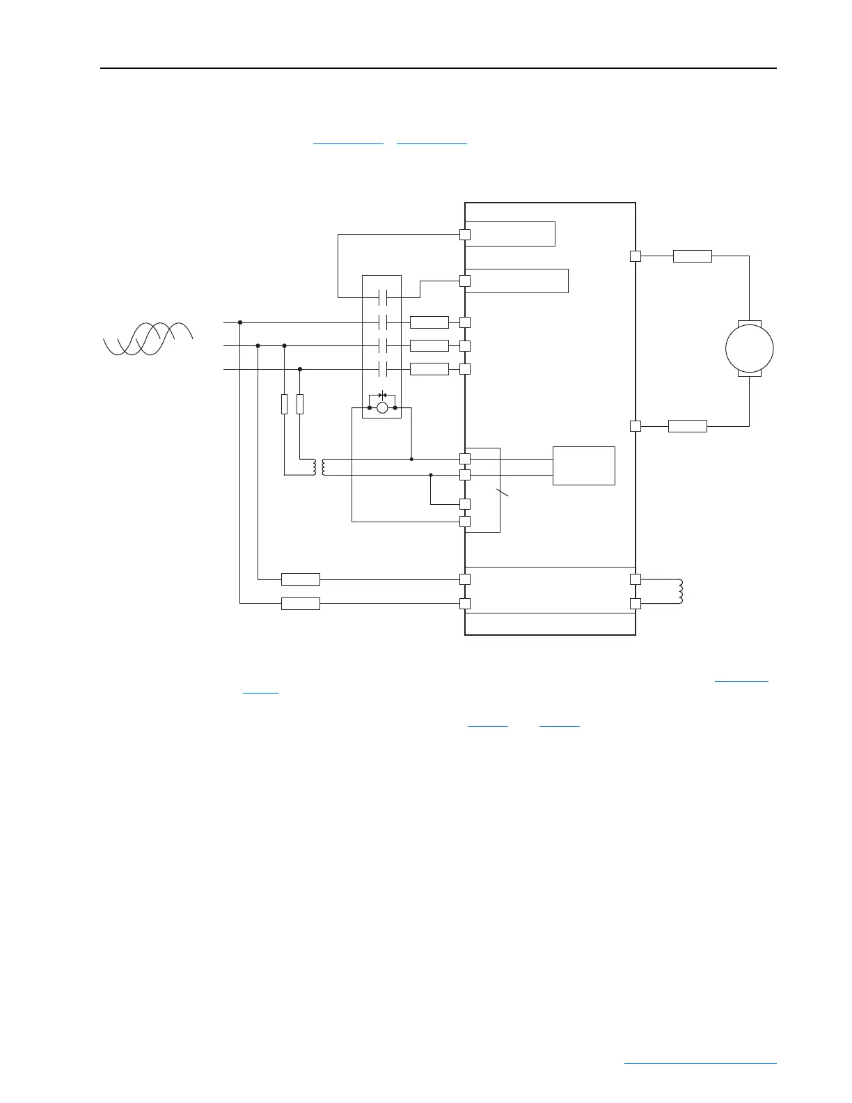
Typical Power Wiring Diagrams
Figure 1.10 - Figure 1.13 represent recommended power wiring
configurations.
Figure 1.10 Power Wiring with AC Input Contactor
M
C
D
M1 AC Contactor
Aux
PowerFlex DC
Drive
36
(3)
34
(1)
(on I/O TB4)
19 (+24V - on I/O TB2)
(N.O. Relay)
Control
Board P/S
460V 115V
V2
U2
F2
A1
A2
35
(3)
U
V
W
3 Phase AC line
L1
L2
L3
13 14
L1
L2
L3
A1
T1
T2
T3
A2
U1
V1
C1
D1
F1
FU1
(2)
FU2
(2)
FU3
FU4
FU5
FU6
FU7
FU8 FU9
Field Power
Terminal Block
Control Power /
Relay Terminal
Block
(1)
Par 140 [Digital In8 Sel] set to 31 “Contactor”
(2)
Armature output fuses are required on four quadrant and are recommended on two quadrant Frame A and B drives. Fuses with Trip Indicator
Switches are recommended for Inverting Fault protection when the motor will be Field Weakened and run above base speed. Refer to Figure 1.13 on
page 1-19.
(3)
Par 1391 [ContactorControl] = 1 “AC Cntctr” and Par 1392 [Relay Out 1 Sel] = 25 “Contactor”. Important: Terminal 35 and 36 are on the Control
Power / Relay Terminal block, NOT the I/O terminal blocks. See Figure 1.20
through Figure 1.22.
 Loading...


