PowerFlex Digital DC Drive User Manual - Publication 20P-UM001C-EN-P - July 2008
1-18 Installation and Wiring
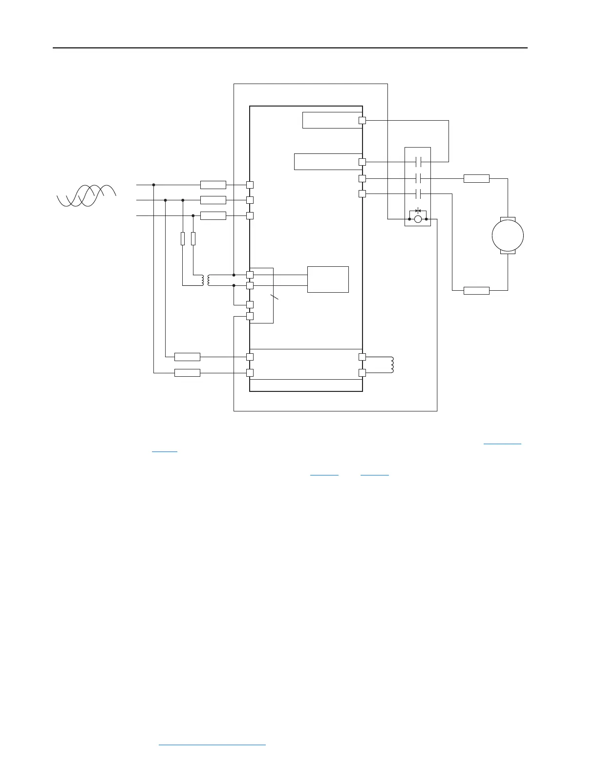
Figure 1.11 Power Wiring with DC Output Contactor
M
C
D
M1 DC Contactor
Aux
PowerFlex DC
Drive
(N.O. Relay)
460V 115V
A1
A2
U
V
W
3 Phase AC line
L1
L2
L3
13 14
L1
L2
A1
T1
T2
A2
U1
V1
FU1
(2)
FU2
(2)
FU3
FU4
FU5
FU6
FU7
FU8 FU9
34 (on I/O TB4)
(1)
19 (+24V on I/O TB2)
36
(3)
Control
Board P/S
V2
U2
35
(3)
Control Power /
Relay Terminal
Block
F2
C1
D1
F1
Field Power
Terminal Block
(1)
Par 140 [Digital In8 Sel] set to 31 “Contactor”
(2)
Armature output fuses are required on four quadrant and are recommended on two quadrant Frame A and B drives. Fuses with Trip Indicator
Switches are recommended for Inverting Fault protection when the motor will be Field Weakened and run above base speed. Refer to Figure 1.13 on
page 1-19.
(3)
Par 1391 [ContactorControl] = 3 “DC Cntctr” and Par 1392 [Relay Out 1 Sel] = 25 “Contactor”. Important: Terminal 35 and 36 are on the Control
Power / Relay Terminal block, NOT the I/O terminal blocks. See Figure 1.20
through Figure 1.22.
 Loading...


