PowerFlex Digital DC Drive User Manual - Publication 20P-UM001C-EN-P - July 2008
1-16 Installation and Wiring
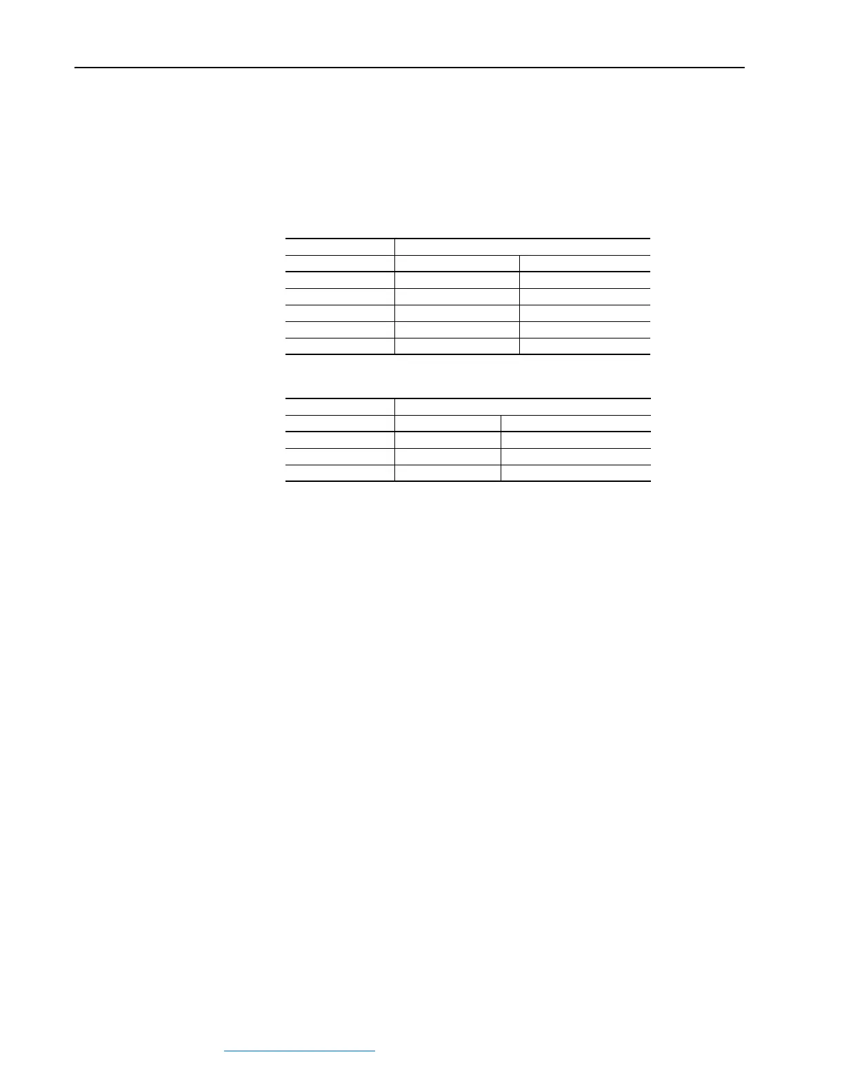
DC Output Voltages
The output voltages below take into account an AC input undervoltage
within the stated tolerance limits and a voltage drop of 4% due to an AC
input line reactor. It is the same as the rated armature voltage suggested for
the connected motor.
Armature Circuit
Field Circuit
AC Input Voltage DC Output Armature Voltage (Terminals C & D)
(Terminals U, V, W) Two Quadrant Drive Four Quadrant Drive
230V ±10 %, 3Ph 260V 240V
400V ±10 %, 3Ph 470V 420V
440V ±10 %, 3Ph 530V 460V
460V ±10 %, 3Ph 560V 480V
480V ±10 %, 3Ph 580V 500V
AC Input Voltage DC Output Field Voltage
(1)
(Terminals C1 & D1)
(1)
The max field voltage is equal to 0.85 x AC input line voltage
(Terminals U1 & V1) Fixed Field Adjustable Field
230V ±15 %, 1Ph 200V 200V
400V ±15 %, 1Ph 310V 310V
460V ±10%, 1Ph 360V 360V
 Loading...


