PowerFlex Digital DC Drive User Manual - Publication 20P-UM001C-EN-P - July 2008
Installation and Wiring 1-35
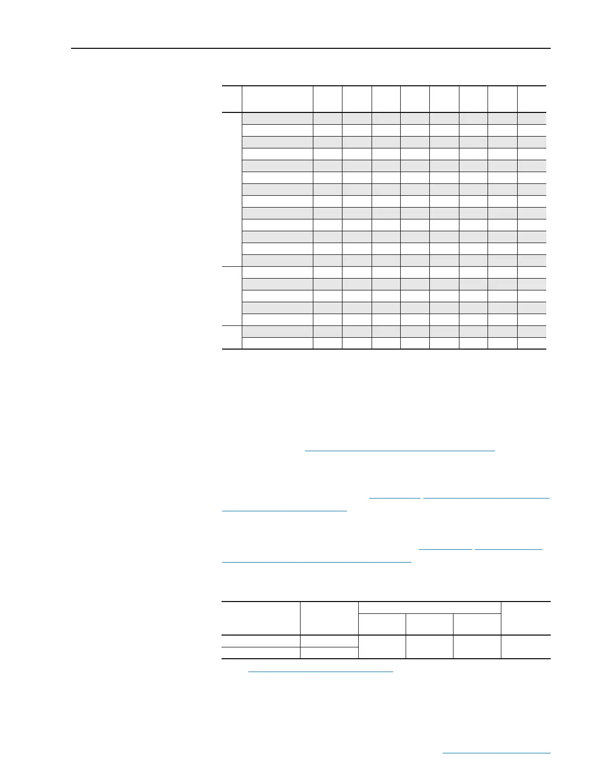
Table 1.O Drives with 460V Input - DIP Switch S15 Configuration
I/O Signal and Control Wiring
Eight (8) digital inputs, four (4) digital outputs, three (3) analog inputs, and
two (2) analog outputs are available on the standard I/O terminal blocks
provided with the drive. One digital input (1-8) must be configured for
“Enable”. Refer to I/O and Control Wire Routing on page 1-42
for proper I/
O wire routing locations.
Additional digital and analog I/O is available when using the optional I/O
Expansion circuit board. Refer to Appendix F
Optional Analog and Digital
I/O Expansion Circuit Board for more information. Also, you can use the
optional 115V AC Converter circuit board to convert 115V AC digital input
signals to 24V DC digital inputs signals to interface with the digital inputs
on the standard I/O terminal blocks. Refer to Appendix G
Optional 115V
AC to 24V DC I/O Converter Circuit Board for more information.
Table 1.P Analog I/O, Digital I/O and DC Analog Tachometer Wire Sizes and Terminal
Specifications
Frame
Drive Current
Rating Code S15-1 S15-2 S15-3 S15-4 S15-5 S15-6 S15-7 S15-8
A
4P1 OFF OFF OFF OFF OFF OFF ON OFF
6P0 ON OFF OFF OFF OFF OFF ON OFF
010 OFF ON OFF OFF OFF OFF ON OFF
014 ON ON OFF OFF OFF OFF ON OFF
019 OFF OFF ON OFF OFF OFF ON OFF
027 ON OFF ON OFF OFF OFF ON OFF
035 OFF ON ON OFF OFF OFF ON OFF
045 ON ON ON OFF OFF OFF ON OFF
052 OFF OFF OFF ON OFF OFF ON OFF
073 ON OFF OFF ON OFF OFF ON OFF
086 OFF ON OFF ON OFF OFF ON OFF
100 ON ON OFF ON OFF OFF ON OFF
129 OFF OFF ON ON OFF OFF ON OFF
B 167 ON OFF ON ON OFF OFF ON OFF
207 OFF ON ON ON OFF OFF ON OFF
250 ON ON ON ON OFF OFF ON OFF
330 OFF OFF OFF OFF ON OFF ON OFF
412 ON OFF OFF OFF ON OFF ON OFF
C
495 OFF ON OFF OFF ON OFF ON OFF
667 ON ON OFF OFF ON OFF ON OFF
Signal Type
Terminal Block
(Terminals)
Wire Size and Type
(1)
(1)
See Cable and Wiring Recommendations on page 1-14 for more information.
Tightening
Torque
N
•m (lb•in)
Flexible
(mm
2
)
Multi-core
(mm
2
)AWG
Analog and Digital I/O TB1 - 4 (1 - 40)
0.140 - 1.500 0.140 - 1.500 26-16 0.4 (3.5)
DC Analog Tach M3 (+ and –)
 Loading...


