PowerFlex Digital DC Drive User Manual - Publication 20P-UM001C-EN-P - July 2008
A-6 Supplemental Drive Information
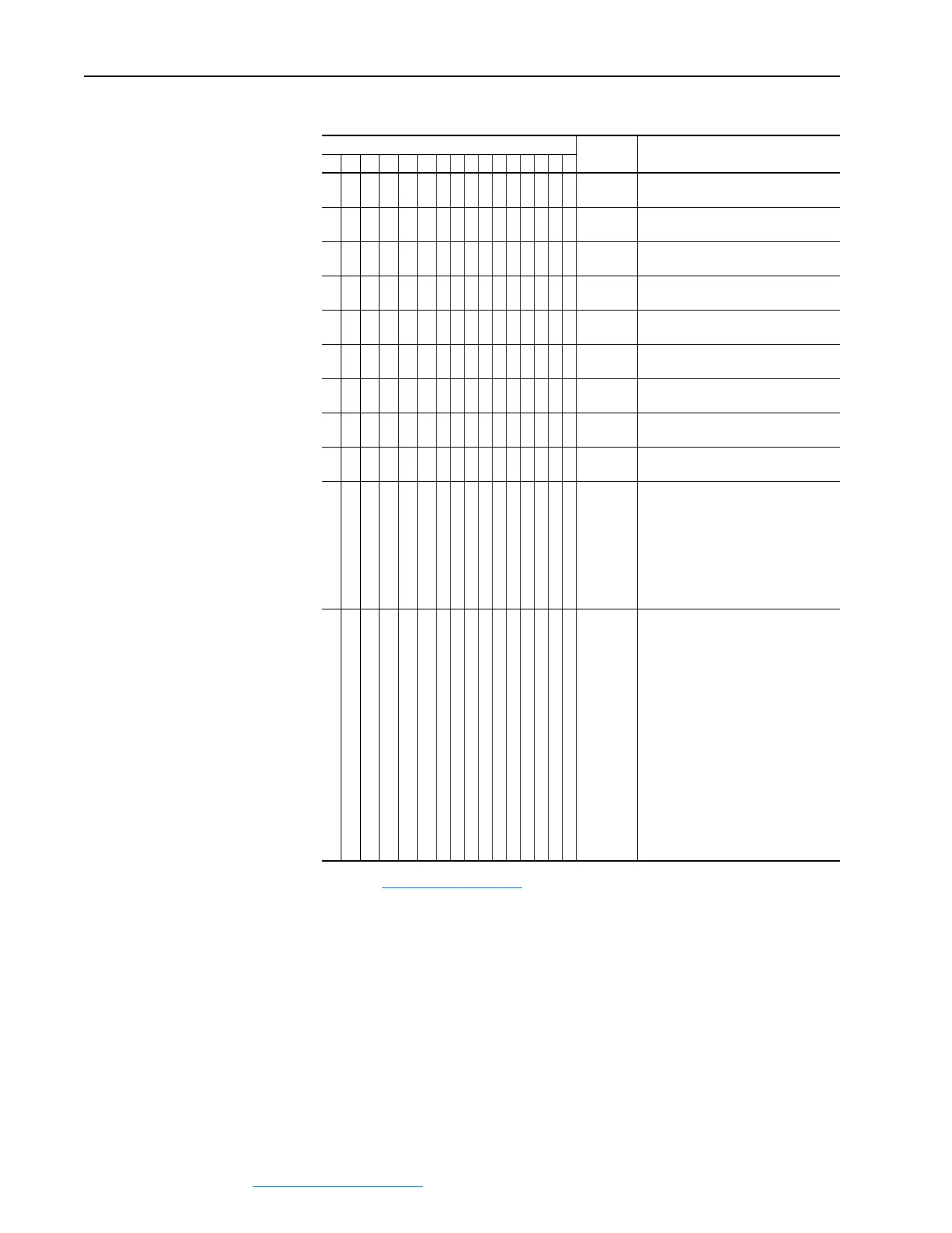
Figure A.2 Logic Status Word
Logic Bits
15 14 13 12 11 10 9 8 7 6 5 4 3 2 1 0 Status Description
x Ready 0 = Not Ready
1 = Ready
x Active 0 = Not Active
1 = Active
x Command
Direction
0 = Reverse
1 = Forward
x Actual
Direction
0 = Reverse
1 = Forward
x Accel 0 = Not Accelerating
1 = Accelerating
x Decel 0 = Not Decelerating
1 = Decelerating
x Alarm 0 = No Alarm
1 = Alarm
x Fault 0 = No Fault
1 = Fault
x At Speed 0 = Not At Reference
1 = At Reference
xxx Local
Control
(1)
(1)
Refer to Masks & Owners on page 3-58 for further information.
000 = Port 0 (TB)
001 = Port 1
010 = Port 2
011 = Port 3
100 = Port 4
101 = Port 5
110 = Reserved
111 = No Local
xxxx Reference
Source
0000 = Spd Ref A Auto
0001 = Spd Ref B Auto
0010 = Preset Spd 2 Auto
0011 = Preset Spd 3 Auto
0100 = Preset Spd 4 Auto
0101 = Preset Spd 5 Auto
0110 = Preset Spd 6 Auto
0111 = Preset Spd 7 Auto
1000 = Term Blk Manual
1001 = DPI 1 Manual
1010 = DPI 2 Manual
1011 = DPI 3 Manual
1100 = DPI 4 Manual
1101 = DPI 5 Manual
1110 = Reserved
1111 = Jog Ref
 Loading...


