PowerFlex Digital DC Drive User Manual - Publication 20P-UM001C-EN-P - July 2008
C-32 Application Notes
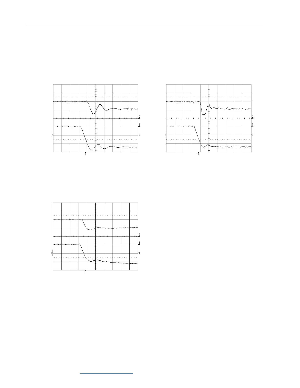
Field Voltage Regulator Tuning Examples
Figure C.12 Field voltage oscillation
Oscillation after a speed change where [Arm Volt Kp] = 10% and
[Arm Volt Ki] = 80%.
Top: Par 234 [Fld Current Pct]
Bottom: Par 233 [Output Voltage]
Figure C.13 Too small of a gain
The armature voltage increases where [Arm Volt Kp] = 3% and
[Arm Volt Ki] = 5%.
Top: Par 234 [Fld Current Pct]
Bottom: Par 233 [Output Voltage]
Figure C.14 Optimal field regulation
After a short transient, the field current and armature voltage are
constant. [Arm Volt Kp] = 40%, [Arm Volt Ki] = 5%.
Top: Par 234 [Fld Current Pct]
Bottom: Par 233 [Output Voltage]
 Loading...


