PowerFlex Digital DC Drive User Manual - Publication 20P-UM001C-EN-P - July 2008
Optional 115V AC to 24V DC I/O Converter Circuit Board G-3
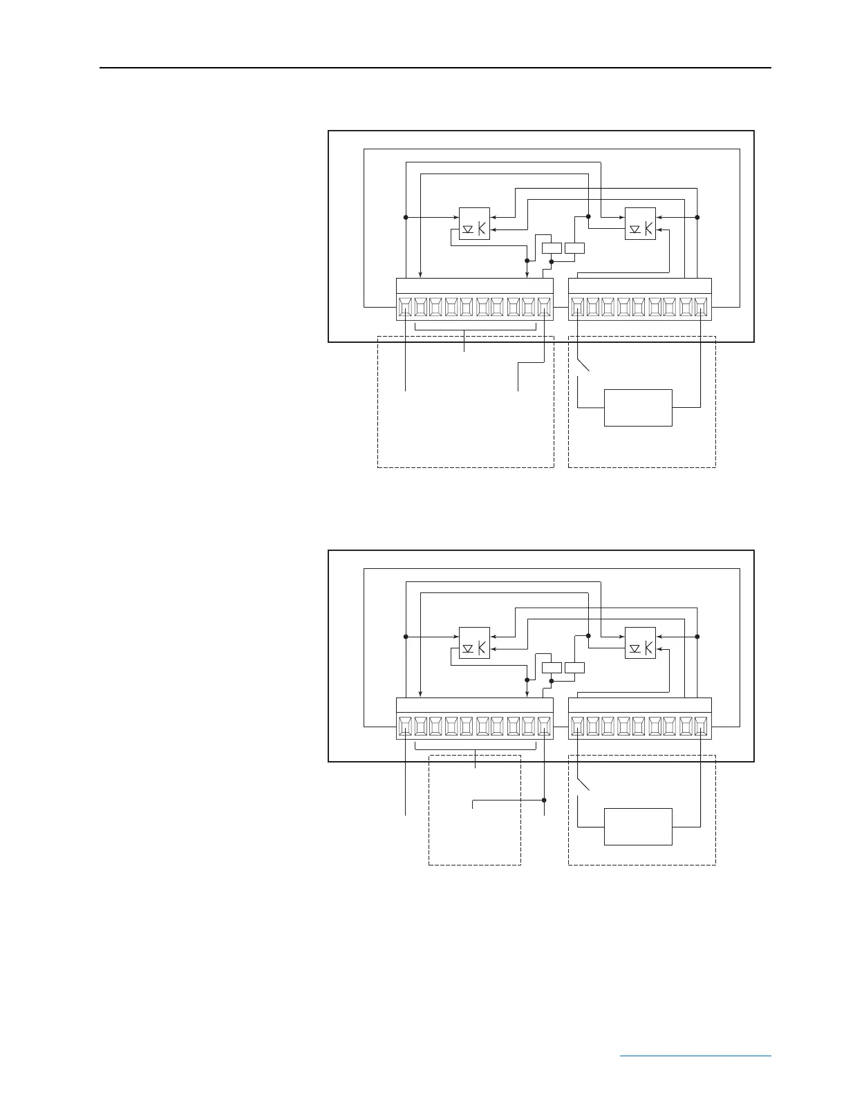
Figure G.2 I/O Converter Board with Internal Supply Wiring Diagram
Figure G.3 I/O Converter Board with External Supply Wiring Diagram
24V 1 2 3 45678 0V 123 45678 COM
Main Control Board
115V AC to 24V DC I/O Board
M_OUT
M_IN
External 115V AC
OPTO OPTO
To Drive
Supplied
+24V DC
(Terminal 19)
on Control Board
To Digital Inputs
(Terminals 12-15, 31-34)
on Control Board
To Digital Input Common
(Terminal 16 or 35)
and 24V Supply Common
(Terminal 18)
on Control Board
15k 15k
Customer WiringInternal Wiring
DC OUTPUT AC INPUT
24V 1 2 3 45678 0V 123 45678 COM
Main Control Board
115V AC to 24V DC I/O Board
M_OUT
M_IN
External 115V AC
OPTO OPTO
From
External
+24V DC
Supply
To Drive Digital Inputs
(Terminals 12-15, 31-34)
To External
24V DC
Supply
Common
To Digital
Input Common
(Terminal 16 or 35)
15k 15k
Customer WiringInternal Wiring
DC OUTPUT AC INPUT
 Loading...


